


 English
  русский
  Español
  Deutsch
  عربى
عربى -
A Rocker Switch is a compact and easy-to-operate manual control component. Its unique rocker-style actuation, combined with a toggle or momentary reset function, allows users to quickly switch circuit...View More >>
-
A micro switch is a small mechanical switch with a fast action mechanism, which is widely used in household appliances, industrial automation, automotive electronics, medical equipment, and other fiel...View More >>
-
The baby stroller gear switch is an innovative product independently developed by our company. We have applied for invention patents both domestically and internationally, which fully demonstrates the...View More >>
-
Push button switches are widely used in various control systems with their diverse structural designs, high-strength material selection, and excellent performance. The products are available in a vari...View More >>
-
The internal structure of the piano key switch mostly adopts a mechanical or light-touch design. Some high-end models use capacitive sensing technology to achieve contactless operation, thereby improv...View More >>
-
The knob switch adopts a high-sensitivity rotary contact structure, which has smooth operation and clear positioning, ensuring that every adjustment is accurate. The product has excellent durability a...View More >>
-
The KM trigger switch is a universal high-current switch designed for high-power power tools, with excellent current carrying capacity and stable performance. The internal fast-action structure ensure...View More >>
-
A door control switch, also known as a door magnetic switch or door status sensor, is a key electrical component widely used in industrial control, security systems, intelligent building automation, a...View More >>
-
The wiring harness is an overall wiring assembly that integrates multiple wires, cables, terminals, and connectors according to specific electrical design and mechanical structure requirements. It is ...View More >>
-
PCB control board is one of the indispensable core components in modern electronic devices. As the brain of the control system, it is widely used in many fields such as industrial automation, consumer...View More >>
NEWS
 Home / News / Industry News / Knob Switch Selection Guide: Types, Wiring, and Applications Explained
Knob Switch Selection Guide: Types, Wiring, and Applications Explained
 2026.09.23
 Industry News
A knob switch looks almost too simple from the outside: a shaft, a grip, and a housing that sits behind a panel. Yet the difference between a rotary control that still feels crisp after ten years and one that turns vague after a few months usually comes down to details hidden inside that housing, such as the detent geometry, the contact material, the shaft tolerance, and the way the terminals are anchored.
We supply rotary control components to equipment makers, and the same questions come up in nearly every project. How many positions do we need? Should the knob click or glide? What happens when the panel gets dusty, or when an operator turns the knob with a gloved hand? This guide walks through those questions in the order a design team actually needs them.
Content
What Is a Knob Switch?
A knob switch is a rotary electromechanical component that changes the state of one or more electrical circuits when a user turns a knob. The knob is the human interface; the body behind the panel holds the contacts, the rotor that drives them, and the terminals where the circuit connects. Turning the knob moves the rotor, and the rotor opens or closes contacts at defined angular positions.
It helps to separate the knob switch from two neighbours that share the same silhouette. A potentiometer also has a shaft and a knob, but its job is to vary resistance continuously rather than to make or break a circuit. A rotary encoder reports rotation as a digital signal and typically has no hard electrical contacts at all. A knob switch, by contrast, is a discrete device: at each designated position it either conducts or it does not, and the operator can feel that position through the detent.
That tactile certainty is not a luxury. On a household appliance, people expect a definite stop rather than a vague sweep. On an industrial panel, a switch that can be nudged out of position by vibration is a genuine safety concern. The feel of the control and the reliability of the circuit are two halves of the same design problem.
How a Knob Switch Works Inside
Open a typical rotary switch and you will find a small set of parts doing a lot of work together.
- The shaft and knob. The shaft transfers the user's torque into the body. It may be round, flatted, or splined, and it may be fixed to the knob by a set screw, a friction fit, or a moulded insert.
- The rotor and cam. The rotor carries the moving contact or contacts. Its profile, the cam, decides exactly when each contact opens and closes as the shaft turns.
- The detent spring and ball. A small spring presses a ball or pin into notches cut into the rotor or a detent plate. This is what produces the familiar click at each position and holds the switch steady against vibration.
- The fixed contacts. These are stamped from copper alloy and often plated with silver or gold, depending on the current level and the operating environment. They are staked or moulded into the housing.
- The housing and terminals. The housing insulates and locates every internal part; the terminals bring the circuit out to the wiring side.
The travel between positions is a deliberate design choice rather than an accident of tooling. A short throw feels quick and precise, which suits small appliances and instruments. A wider throw feels more deliberate and is easier to operate with gloves, which is why it appears so often on power tools and control cabinets.
Common Types of Knob Switch
Most rotary controls on the market fall into a handful of practical categories. The table below groups them by switching behaviour and by the applications where each type tends to earn its place.
| Type | Switching Behaviour | Typical Application |
|---|---|---|
| On-off rotary switch | Two stable positions, open and closed | Small appliances, fans, lighting fixtures |
| Multi-position selector | Three or four stable positions in one pole | Mode selection, instrument front panels |
| Cam-operated rotary switch | Several independent contact groups switching together | Industrial control cabinets, test equipment |
| Encoder-style knob switch | Continuous rotation with a push-to-select function | Human-machine interfaces, audio and video gear |
| Illuminated knob switch | Rotation plus an integrated indicator lamp | Control panels, HVAC equipment, machine status |
Within each category the practical differences are smaller than the labels suggest. Two on-off rotary switches can look identical and still behave very differently once you measure operating torque, contact resistance, and the number of cycles before the detent softens.
Where Knob Switches Are Used
Because a rotary control combines a mechanical feel with an electrical function, it turns up wherever an operator needs to choose a state without looking closely at a screen.
- Household appliances. Fan speed, oven mode, and timer selection still rely on rotary controls because they are readable at a glance and work with wet or greasy hands.
- Industrial control panels. Selector knobs let a technician choose between manual, off, and automatic without navigating a menu, which matters during fault-finding.
- Power tools and garden equipment. Here the knob must survive dust, vibration, and gloves, and it often shares a housing with switches rated for higher currents.
- Office and computer peripherals. Compact rotary controls appear in printers, audio equipment, and adjustable desk hardware.
- Medical and laboratory instruments. Precise, repeatable positions matter more than speed, and the control is often expected to be cleanable.
Notice how the same component family serves both a kitchen appliance and a machine panel. What changes is not the basic principle but the specification around it: current rating, sealing, operating torque, and the material of the knob itself.
How to Choose the Right Knob Switch
Selection usually starts with the electrical requirement and ends with the feel of the control. Working through the list below in order saves a great deal of rework later.
- Electrical rating. Confirm the voltage, current, and whether the load is resistive or inductive. Inductive loads such as motors and solenoids demand more contact margin than a resistor of the same wattage.
- Positions and circuit configuration. Count the states the operator must select, then decide how many poles need to switch at the same time.
- Operating torque and detent feel. This is where prototypes earn their keep. A knob that feels right on the bench may feel heavy once the panel and the knob are fitted.
- Shaft and knob interface. Shaft diameter, length, flat orientation, and the fixing method all affect how the finished control feels and how long it stays tight.
- Panel mounting. Bushing nut, snap-in, or screw fixing, along with the panel cut-out tolerance and the available depth behind the panel.
- Environmental protection. Dust, moisture, cleaning agents, and temperature range should be stated explicitly rather than assumed.
- Service life. Ask for a cycle figure at the actual load, not a no-load figure.
If you would rather start from an existing design than from a blank sheet, our rotary line covers four distinct behaviour profiles, and the differences between them are mainly about feel and repeatability.
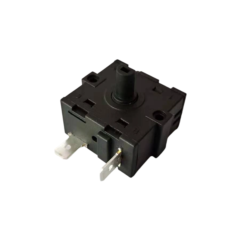 RS-111 Intuitive and easy to use Knob switchSafety certification technical data: This product has TUVView Product →
The RS111 keeps operation direct and unmistakable, with a straightforward turning action that suits appliances and small instruments where users simply need an obvious on or off position.
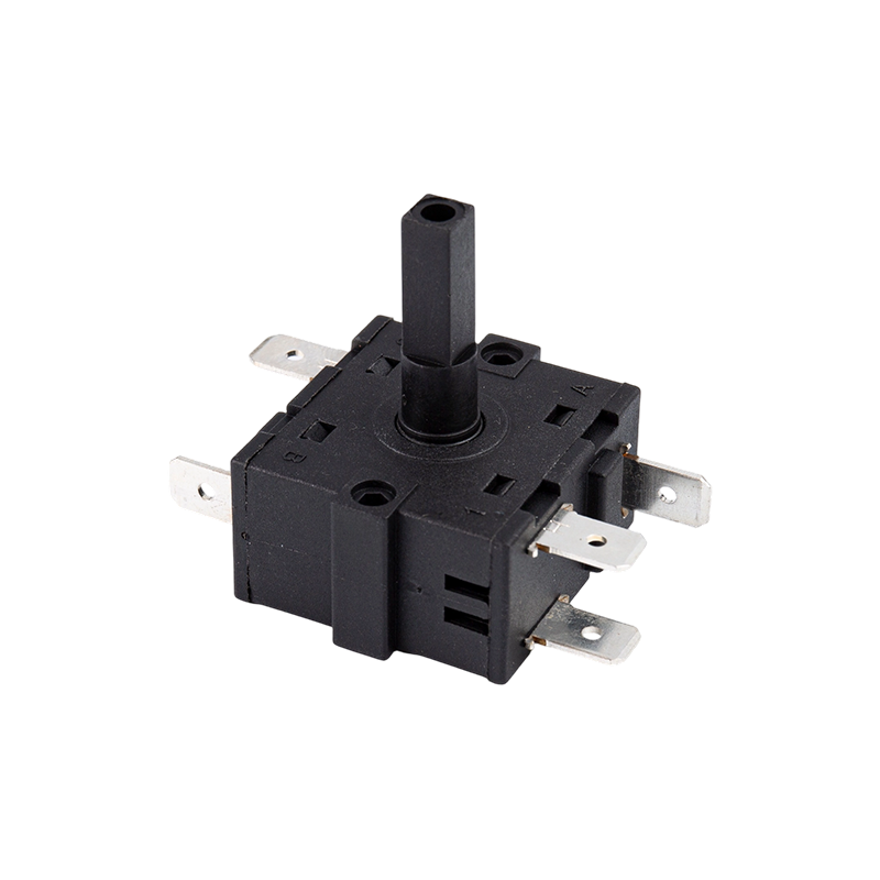 RS-112 Reliable and durable Knob switchSafety certification technical data: This product has TUVView Product →
The RS112 shifts the emphasis toward durability, with contact and bearing details chosen for equipment that is used every day and expected to keep its original feel.
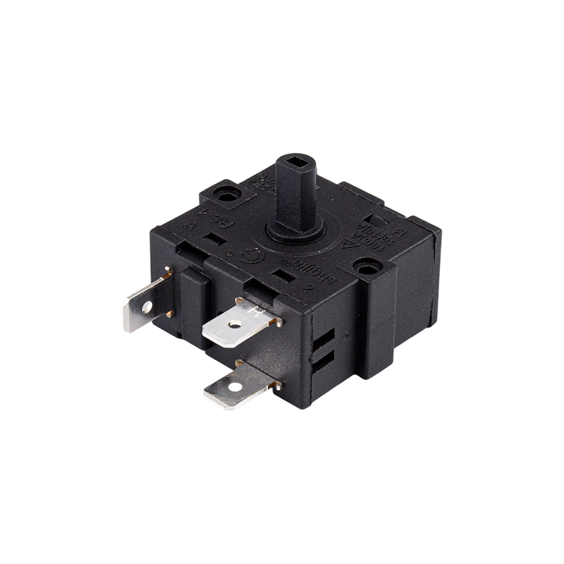 RS-113 Responsive Knob switchSafety certification technical data: This product has TUVView Product →
The RS113 answers faster, with a lighter detent and a more responsive action for controls that operators adjust frequently during a working cycle.
Wiring and Installation Notes
Most field failures we hear about are not caused by the switch itself but by how it was installed. A few habits prevent the majority of them.
- Keep soldering time short and use the recommended iron temperature. Terminals are anchored in plastic, and excess heat transfers into the housing.
- Support the terminal during soldering so the contact inside the body is not stressed.
- Avoid side loads on the shaft when fitting the knob. Pressing a knob onto a shaft with a hammer is a reliable way to damage the detent.
- Tighten the mounting nut to the recommended torque. Over-tightening distorts the bushing and changes the operating torque.
- Leave enough room behind the panel for the wiring to bend without pulling on the terminals.
What to Check on Quality and Reliability
A sample can feel perfect on a bench and still fail in the field once vibration, heat cycling, and rough handling are added to the picture. Before committing to volume production, it is worth asking a supplier a few direct questions.
- How is rotation life measured, and at what electrical load?
- What are the contact resistance and insulation resistance values, and how are they verified?
- Is there a dielectric strength test on every production batch?
- How are the shaft dimensions and detent torque controlled across a production run?
- Can the supplier trace a finished switch back to its material lots?
These are reasonable questions for any component that will sit behind a panel for years, and a supplier who can answer them clearly is usually the one who will still be answering the phone after the first shipment. We have written a longer selection guide that goes into wiring configurations and specification detail if you want to compare options side by side.
For a closer look at the full range, including variants that differ in shaft type, mounting style, and detent strength, browse the knob switch product family. If you would rather read up on configuration choices before you talk to anyone, our technical article on knob switch types, wiring, and selection criteria covers the same ground in more detail.
Frequently Asked Questions
Is a knob switch the same as a rotary switch?
In everyday use the terms overlap. Technically, a rotary switch is the switching mechanism, while a knob switch describes the complete assembly of mechanism plus shaft plus knob. When you specify a part, what matters is the number of positions, the contact configuration, and the load rating.
How do I know how many positions I need?
List every state the operator must select and add any state that service personnel need. If the count exceeds four, a cam-operated rotary switch or an encoder-style control usually becomes the more practical route.
Can a knob switch be sealed against dust and water?
Yes. Sealing is achieved with an O-ring or gasket around the shaft, a sealed housing, and potted or gasketed terminals. The achievable protection level depends on the panel design as much as on the switch, so the two should be developed together.
What makes a knob switch feel loose over time?
Usually wear in the detent mechanism or a bushing that was over-tightened during installation. Choosing a switch rated well above the expected cycle count and following the mounting torque specification prevents most of it.
A knob switch is a small part of a finished product, but it is often the part an operator touches most. Getting the electrical rating right is straightforward; getting the feel right takes a little more thought and, ideally, a prototype in someone's hand before the tooling is cut. If you are working through that decision now, our team is happy to talk through positions, torque, and mounting options and help you narrow the range down to a part that fits the way your product is actually used.

A Appliance Switches Manufacturer that has been focusing on the development, production and sales of Switches for 21 years;
Products Links
Contact Information
Tel: +86-021-33752188
Phone: +86-13524812989
E-Mail: [email protected]
[email protected]
[email protected]Address: No. 580 Shenzhou Road, Fengxian District, Shanghai, China

