


 English
  русский
  Español
  Deutsch
  عربى
عربى -
A Rocker Switch is a compact and easy-to-operate manual control component. Its unique rocker-style actuation, combined with a toggle or momentary reset function, allows users to quickly switch circuit...View More >>
-
A micro switch is a small mechanical switch with a fast action mechanism, which is widely used in household appliances, industrial automation, automotive electronics, medical equipment, and other fiel...View More >>
-
Push button switches are widely used in various control systems with their diverse structural designs, high-strength material selection, and excellent performance. The products are available in a vari...View More >>
-
The internal structure of the piano key switch mostly adopts a mechanical or light-touch design. Some high-end models use capacitive sensing technology to achieve contactless operation, thereby improv...View More >>
-
The baby stroller gear switch is an innovative product independently developed by our company. We have applied for invention patents both domestically and internationally, which fully demonstrates the...View More >>
-
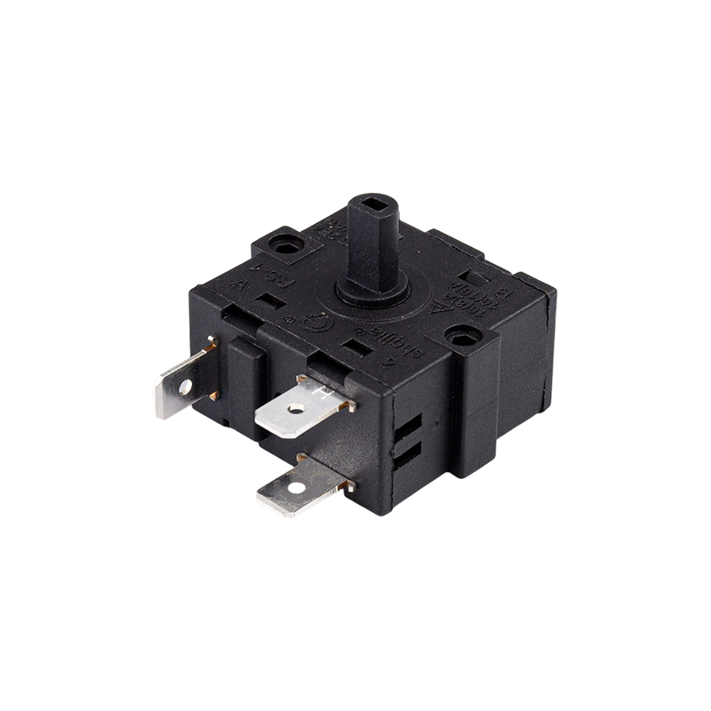
The knob switch adopts a high-sensitivity rotary contact structure, which has smooth operation and clear positioning, ensuring that every adjustment is accurate. The product has excellent durability a...View More >>
-
The KM trigger switch is a universal high-current switch designed for high-power power tools, with excellent current carrying capacity and stable performance. The internal fast-action structure ensure...View More >>
-
A door control switch, also known as a door magnetic switch or door status sensor, is a key electrical component widely used in industrial control, security systems, intelligent building automation, a...View More >>
-
The wiring harness is an overall wiring assembly that integrates multiple wires, cables, terminals, and connectors according to specific electrical design and mechanical structure requirements. It is ...View More >>
-
PCB control board is one of the indispensable core components in modern electronic devices. As the brain of the control system, it is widely used in many fields such as industrial automation, consumer...View More >>
NEWS

Knob Switches: Types, Wiring Configurations & Selection Guide
 2026.05.19
 Industry News
Content
- 1 What Knob Switches Are and Where They're Used
- 2 Types of Knob Switches by Operating Mechanism
- 3 Poles and Positions: Reading Rotary Switch Configurations
- 4 Electrical Ratings: Voltage, Current, and Load Type
- 5 Mounting Configurations and Panel Installation
- 6 IP Ratings and Environmental Protection for Knob Switches
- 7 Common Faults in Knob Switches and How to Diagnose Them
- 8 What to Check When Sourcing Knob Switches for Production or Replacement
What Knob Switches Are and Where They're Used
Knob switches — more formally known as rotary switches or rotary knob switches — are electromechanical switching devices operated by turning a knob to select between two or more positions. Unlike toggle switches that move between on and off states with a lever, or pushbutton switches that actuate on a single press, knob switches rotate through a defined arc to connect different circuit paths depending on the position selected. The physical knob provides tactile feedback and clear positional indication, making them intuitive to operate in both consumer and industrial environments.
The application range for rotary knob switches is broad. In household appliances, they control heating elements on electric stoves, fan speed settings on ovens and range hoods, washing machine cycle selectors, and temperature controls on water heaters. In industrial settings, they serve as mode selectors on control panels, function selectors on test and measurement equipment, speed controllers on motor drives, and power source selectors on electrical distribution boards. In audio and electronics, knob switches appear as input selectors, tone controls, and range selectors on amplifiers, radios, and oscilloscopes. The common thread across all these applications is the need to select reliably between a defined set of circuit states — something a rotary knob switch does more clearly and durably than most alternatives.
Understanding the different types of knob switches, their electrical specifications, and their mechanical construction is essential for anyone selecting replacement components, specifying switches for a new design, or troubleshooting a failed control panel. The variety in this product category is wider than casual familiarity with the knob switches on a kitchen stove might suggest.
Types of Knob Switches by Operating Mechanism
Not all knob switches operate on the same internal mechanism, and the mechanism determines how the switch detects position, what switching action it performs, and how reliable it is over its service life. The three principal operating mechanisms used in rotary knob switches are detent-action mechanical contact, cam-operated contact, and wafer-type contact arrays.
Detent Rotary Switches
Detent rotary switches use a spring-loaded ball or blade that clicks into notched positions as the knob is turned, providing audible and tactile confirmation that a specific position has been reached and held. The detent mechanism prevents the knob from resting between positions — it either snaps fully into the next position or stays in the current one. This positive positioning is critical in switching applications where intermediate positions would connect incorrect circuit paths or create undefined switching states. Most household appliance knob switches and panel-mount selector switches use detent mechanisms. The spacing between detent positions is defined by the switch's stop count — typically between 2 and 12 positions in standard catalog switches — and the arc swept between the first and last position is usually between 120 and 300 degrees depending on position count and design.
Cam-Operated Rotary Switches
Cam-operated knob switches use a rotating cam profile to open and close individual contact pairs as the shaft turns. The cam geometry determines exactly which contacts are made or broken at each position, and complex switching sequences — including making before breaking, breaking before making, or simultaneous contact transitions — can be programmed into the cam profile. Cam-operated rotary switches are widely used in industrial control panels where specific sequences of contact operation are needed across multiple positions, such as motor forward-off-reverse selectors, multi-speed controllers, and instrumentation range selectors. They are mechanically robust and capable of handling higher contact currents than wafer-type switches of equivalent physical size.
Wafer-Type Rotary Switches
Wafer-type rotary switches consist of one or more circular insulating wafers, each carrying a set of contact pads arranged around the perimeter. A central rotor with a wiper contact rotates with the shaft and sequentially touches each contact pad as the knob is turned. Multiple wafers can be stacked on a single shaft to create switches with multiple independent circuits (poles) all operated by the same knob. Wafer switches are the standard format for multi-pole, multi-position rotary knob switches used in electronics — test equipment range selectors, audio input selectors, and circuit configuration switches. They handle lower currents than cam-operated industrial switches but offer high positional resolution and the flexibility of stacking multiple wafers for complex switching requirements.
Poles and Positions: Reading Rotary Switch Configurations
Knob switches are specified by their pole count and position count, expressed as a combination such as 1P6T (one pole, six throws), 2P4T, 3P3T, and so on. Understanding what poles and positions mean in a rotary switch context is necessary for selecting the right switch for any given circuit requirement.
A pole represents one independent circuit path controlled by the switch. A single-pole (1P) rotary switch controls one circuit — rotating the knob connects the common terminal to one of several output terminals in sequence. A two-pole (2P) switch controls two independent circuits simultaneously with the same knob rotation — both circuits switch together but operate independently of each other electrically. Multi-pole rotary switches are used when multiple circuits must be switched in synchrony — for example, switching both the live and neutral conductors of multiple circuits simultaneously on a rotary power selector.
Positions (also called throws or steps) represent the number of distinct switching states the knob provides. A 1P6T switch has one pole with six output positions — rotating the knob connects the single input to one of six possible outputs. Position count determines how many distinct settings the switch provides and, combined with pole count, defines the total number of circuit connections the switch manages.
| Configuration | Poles | Positions | Typical Application |
| 1P2T | 1 | 2 | Simple on/off or A/B source selector |
| 1P4T | 1 | 4 | 4-speed fan selector, 4-input audio switch |
| 1P6T | 1 | 6 | Multi-range meter selector, 6-position mode switch |
| 2P3T | 2 | 3 | 3-speed motor with two-circuit control |
| 3P4T | 3 | 4 | Industrial control panel mode selector |
| 4P3T | 4 | 3 | Power source transfer switch, multi-circuit selector |
When selecting a replacement rotary knob switch, matching both the pole count and position count of the original is essential — a switch with fewer positions than required will leave some circuit states inaccessible, while one with more poles than needed simply leaves unused terminals. The physical footprint, shaft diameter, and panel cutout dimensions also need to match the original for a drop-in replacement.
Electrical Ratings: Voltage, Current, and Load Type
The electrical ratings of a knob switch define the maximum voltage and current it can safely switch without contact damage, arcing, or insulation breakdown. Applying a switch outside its ratings is a reliability and safety risk — contacts erode faster, arcing causes carbon deposits that increase contact resistance, and in severe cases insulation failure can cause short circuits or fire. Matching the switch rating to the actual circuit conditions is a non-negotiable requirement in any switching application.
Voltage Rating
Rotary knob switches are rated for maximum operating voltage — the highest voltage that can be safely present across open contacts or applied through closed contacts. Most general-purpose knob switches carry ratings of 125VAC, 250VAC, or 600VAC for AC applications, and separate DC voltage ratings that are typically lower than the AC rating for the same switch. DC switching is more demanding on contacts than AC switching because DC arcs don't self-extinguish at current zero-crossings the way AC arcs do — they sustain and cause more contact erosion. Always verify both the AC and DC voltage ratings separately when the switch will be used in a DC circuit.
Current Rating and Load Type
Current ratings for knob switches are typically provided for specific load types, because the switching behavior of different loads creates different levels of electrical stress on the contacts. Resistive loads — electric heaters, incandescent lamps — switch cleanly and the current rating can be used at face value. Inductive loads — motors, transformers, relays, solenoids — generate voltage spikes when the circuit is broken (back-EMF), which causes arcing at the contacts and accelerates wear. Capacitive loads — switching power supplies, capacitor banks — draw very high inrush currents at turn-on. Most switch manufacturers derate the current rating for inductive and capacitive loads — often to 20–50% of the resistive current rating. Check the datasheet for load-specific ratings rather than assuming the headline current figure applies to all load types.
Contact Material and Its Effect on Performance
The contact material in a rotary knob switch determines its resistance to arcing erosion, welding under high inrush current, and oxidation in humid or contaminated environments. Silver alloy contacts (silver cadmium oxide, silver tin oxide) are standard in power-rated switches and provide good conductivity combined with arc erosion resistance. Gold-plated contacts are used in signal-level switches — audio selectors, instrumentation range switches — where the very low contact resistance and oxidation resistance of gold ensures reliable switching of millivolt-level signals that silver contacts would corrupt with oxide film resistance. Using a gold-contact signal switch in a power circuit, or a silver-contact power switch in a low-level signal circuit, both produce suboptimal results for different reasons.
Mounting Configurations and Panel Installation
Knob switches are available in several mounting configurations that determine how they attach to control panels, enclosures, or PCBs. Selecting the right mounting type for the installation environment affects both the mechanical security of the switch and the ease of installation and replacement.
Panel Mount (Bushing Mount)
Panel-mount rotary knob switches are the most common type for control panels, appliance front panels, and equipment enclosures. The switch body protrudes through a circular hole in the panel, and a threaded bushing with a locking nut secures the switch from the front face. The shaft extends through the panel for knob attachment. Panel hole diameters for standard knob switches are typically 16mm, 22mm, or 30mm — with 22mm being the most common in industrial control panels, where it is a standard format shared with pushbutton switches and indicator lights to allow mixed-device panel layouts. The IP (ingress protection) rating of a panel-mount switch applies to the front face when properly mounted — the switch body inside the panel is not protected unless the enclosure itself provides environmental protection.
PCB Mount
PCB-mount rotary switches have pins that insert directly into a printed circuit board and are soldered in place. They are compact, eliminate the need for wiring, and integrate the switching function directly into the circuit assembly. PCB-mount knob switches are used in consumer electronics, test equipment, and embedded control systems where the switch is part of the main circuit board assembly rather than a remote panel component. The mechanical stress of knob operation is transferred to the PCB solder joints and mounting pads, so PCB footprint design and solder quality are important reliability factors for this mounting type.
DIN Rail Mount
DIN rail-mounted rotary selector switches clip onto standard 35mm DIN rail inside electrical enclosures and distribution boards. This format is common in industrial control cabinets where the knob selector switch controls modes or sources from inside the panel door. DIN rail mounting eliminates individual panel drilling requirements and allows the switch to be repositioned along the rail for layout changes. The operating knob typically extends through or is accessible via the cabinet door, which may require door cutouts coordinated with the switch position.
IP Ratings and Environmental Protection for Knob Switches
The operating environment significantly affects which knob switch is appropriate for a given installation. A switch that performs perfectly in a clean, dry indoor control panel will fail rapidly if installed in a wet outdoor enclosure, a dusty industrial machine, or a food processing environment exposed to wash-down cleaning. IP (Ingress Protection) ratings define how well a switch resists the entry of solid particles and liquids, and they are an essential selection criterion for any non-office environment.
| IP Rating | Solid Protection | Liquid Protection | Typical Application |
| IP40 | 1mm+ objects | No water protection | Indoor dry environments, consumer electronics |
| IP54 | Dust partial protection | Splash from any direction | Light industrial, outdoor sheltered panels |
| IP65 | Dust tight | Low-pressure water jets | Outdoor panels, dusty industrial environments |
| IP66 | Dust tight | High-pressure water jets | Wash-down areas, food processing, marine |
| IP67 | Dust tight | Temporary immersion to 1m | Outdoor equipment, wet industrial processes |
| IP69K | Dust tight | High-pressure, high-temp steam cleaning | Food and beverage, pharmaceutical, hygiene-critical |
It is important to note that IP ratings for panel-mount knob switches typically apply to the front face only when the switch is correctly installed in a panel of appropriate thickness using the supplied sealing gasket. The switch body inside the panel relies on the enclosure for environmental protection. Always verify whether the IP rating quoted is for the switch face only or for the complete switch assembly, and confirm that the installation conditions — panel thickness, gasket compression, and mounting hardware torque — match the requirements for the stated IP rating to be valid.
Common Faults in Knob Switches and How to Diagnose Them
Knob switches are mechanically simple and generally reliable, but they do fail — most commonly through contact wear, oxidation, mechanical damage, or contamination of the contact mechanism. Understanding the failure modes and how to diagnose them speeds up troubleshooting and prevents unnecessary replacement of components that aren't actually faulty.
- Intermittent or no circuit in one position: The most common fault. Usually caused by worn, oxidized, or contaminated contacts at a specific position. Test with a multimeter in continuity mode — rotate the knob through each position and check resistance across the relevant terminals. A good contact should show near-zero resistance; a worn or oxidized contact shows elevated resistance or open circuit. Contacts can sometimes be cleaned with contact cleaner spray, but mechanical wear is not reversible.
- Switch feels loose or doesn't click into position: The detent spring or ball has weakened or broken, allowing the knob to rest between positions. This creates undefined switching states. The switch needs replacement — detent mechanisms are not field-serviceable on most knob switch designs.
- Knob spins freely without switching: The shaft-to-knob connection has failed — either the set screw has loosened, the knob's internal spline has stripped, or the shaft itself has sheared inside the switch body. Inspect the knob attachment first; if the shaft turns freely inside the switch body, the internal mechanism has failed and the switch needs replacement.
- All positions show open circuit: Either the common terminal connection has failed, or the wiper contact inside the switch has broken or corroded completely. Verify wiring integrity at the common terminal first before concluding the switch has failed internally.
- Switch works but causes circuit malfunction: Elevated contact resistance from oxidation or contamination can cause voltage drops across the switch contact that affect sensitive circuits. A healthy switch contact should measure below 100 milliohms; above 1 ohm suggests significant oxidation. In power circuits this may not be perceptible, but in signal or control circuits even modest contact resistance can cause incorrect operation.
- Physical damage to the switch body or knob: Impact damage, over-torquing, or forced rotation beyond the stop positions can crack the switch body, bend the shaft, or shear the internal stop mechanism. Inspect for visible cracks around the bushing area and verify that the shaft rotates smoothly without grinding or binding before concluding the switch is electrically functional.
What to Check When Sourcing Knob Switches for Production or Replacement
For engineers specifying knob switches for new designs, procurement teams sourcing production quantities, or maintenance managers managing replacement stock for installed equipment, the specification process requires confirming more than just the headline electrical ratings. A complete specification covers mechanical, environmental, and compliance requirements that determine whether the switch will perform reliably in service and meet applicable regulatory standards.
- Mechanical life rating: Specified in number of operating cycles — typically 10,000 to 100,000 cycles for standard industrial knob switches, and up to 1,000,000 cycles for high-reliability versions. Match the mechanical life rating to the expected operating frequency over the design service life of the equipment.
- Operating torque: The force required to rotate the knob between positions affects operator ergonomics and the suitability of the switch for applications where accidental operation needs to be prevented. Switches with higher operating torque reduce inadvertent position changes in vibrating environments but require more deliberate operator effort.
- Shaft dimensions and knob compatibility: Shaft diameter (most commonly 6mm in metric designs), shaft length, and shaft profile (round, D-flat, or splined) must match the knob being used. For replacement applications, confirm shaft profile matches the original — a D-flat shaft requires a D-flat knob bore, and substituting a round shaft without a flat will result in the knob spinning on the shaft.
- Safety and compliance certifications: For switches used in mains-voltage appliances, industrial control panels, or equipment sold in regulated markets, confirm that the switch carries relevant certifications — UL listing for North American markets, CE marking and VDE or TÜV approval for European markets, CCC for China. Uncertified switches may fail compliance audits and create product liability exposure.
- Operating temperature range: Standard knob switches are typically rated for –25°C to +85°C. Applications in extreme cold (outdoor equipment in cold climates) or elevated temperature environments (inside appliance enclosures near heating elements) may require switches with extended temperature ratings and materials specified accordingly.
- Availability of position indicator and locking accessories: Many industrial knob switch ranges offer accessory position indicator discs, protective collars, key-lock mechanisms, and padlockable versions for applications where inadvertent or unauthorized operation needs to be prevented. Confirm accessory availability from the chosen manufacturer before committing to a switch range for a design that requires these features.


A Appliance Switches Manufacturer that has been focusing on the development, production and sales of Switches for 21 years;
Products Links
Contact Information
Tel: +86-021-33752188
Phone: +86-15902103688
E-Mail: [email protected]
[email protected]
[email protected]Address: No. 580 Shenzhou Road, Fengxian District, Shanghai, China

