


 English
  русский
  Español
  Deutsch
  عربى
عربى -
A Rocker Switch is a compact and easy-to-operate manual control component. Its unique rocker-style actuation, combined with a toggle or momentary reset function, allows users to quickly switch circuit...View More >>
-
A micro switch is a small mechanical switch with a fast action mechanism, which is widely used in household appliances, industrial automation, automotive electronics, medical equipment, and other fiel...View More >>
-
Push button switches are widely used in various control systems with their diverse structural designs, high-strength material selection, and excellent performance. The products are available in a vari...View More >>
-
The internal structure of the piano key switch mostly adopts a mechanical or light-touch design. Some high-end models use capacitive sensing technology to achieve contactless operation, thereby improv...View More >>
-
The baby stroller gear switch is an innovative product independently developed by our company. We have applied for invention patents both domestically and internationally, which fully demonstrates the...View More >>
-
The knob switch adopts a high-sensitivity rotary contact structure, which has smooth operation and clear positioning, ensuring that every adjustment is accurate. The product has excellent durability a...View More >>
-
The KM trigger switch is a universal high-current switch designed for high-power power tools, with excellent current carrying capacity and stable performance. The internal fast-action structure ensure...View More >>
-
A door control switch, also known as a door magnetic switch or door status sensor, is a key electrical component widely used in industrial control, security systems, intelligent building automation, a...View More >>
-
The wiring harness is an overall wiring assembly that integrates multiple wires, cables, terminals, and connectors according to specific electrical design and mechanical structure requirements. It is ...View More >>
-
PCB control board is one of the indispensable core components in modern electronic devices. As the brain of the control system, it is widely used in many fields such as industrial automation, consumer...View More >>
NEWS
 Home / News / Industry News / Rocker Switches Explained: Configurations, Ratings, and How to Pick the Right One
Rocker Switches Explained: Configurations, Ratings, and How to Pick the Right One
 2026.03.25
 Industry News
Content
- 1 What Rocker Switches Are and How They Work
- 2 Rocker Switch Configurations: SPST, SPDT, DPST, and DPDT Explained
- 3 Understanding Rocker Switch Ratings: Voltage, Current, and AC vs. DC
- 4 Illuminated Rocker Switches: Types, Wiring, and When to Use Them
- 5 IP Ratings and Environmental Protection for Rocker Switches
- 6 Panel Mounting: Cutout Dimensions, Busbar Systems, and Secure Installation
- 7 Common Applications and How to Match the Right Rocker Switch to the Job
What Rocker Switches Are and How They Work
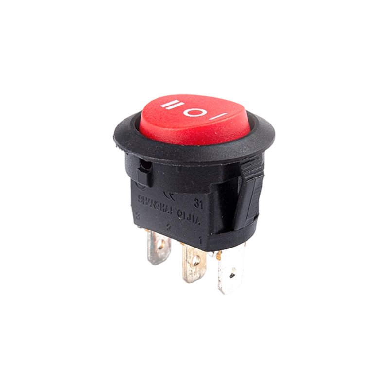
A rocker switch is a type of electrical switch that operates by pressing one side of a pivoting actuator — the rocker — to make or break an electrical circuit. When you press one end down, the opposite end rises, and the internal contact mechanism either closes or opens the circuit path. Release the pressure and the switch stays in position, unlike a momentary pushbutton that returns to its resting state when released. This latching behavior is what makes rocker switches the default choice for power on/off controls across consumer electronics, industrial equipment, marine applications, and automotive accessories.
The internal mechanism is straightforward: a spring-loaded contact arm or ball detent holds the rocker firmly in each position. When the actuator pivots past the mechanical center point, the spring snaps it into the opposite position, producing the characteristic tactile click that confirms a complete switching action. This snap-action mechanism ensures that the internal contacts do not hover in a partially open state — a critical design requirement because partial contact creates arcing, which accelerates contact wear and can cause intermittent circuit behavior. The snap-action principle is what separates a well-engineered rocker switch from a marginal one.
Rocker switches are distinguished from toggle switches primarily by their form factor. Toggle switches use a protruding lever that flips between positions, while rocker switches use a flat or slightly contoured paddle that sits flush or nearly flush with the mounting panel. This makes rocker switches easier to operate with a gloved hand, more resistant to accidental actuation from brushing contact, and generally more appropriate for panel-mount applications where a clean, professional appearance is required.
Rocker Switch Configurations: SPST, SPDT, DPST, and DPDT Explained
The electrical configuration of a rocker switch — described by its pole and throw count — defines how many independent circuits it controls and how many positions each circuit can connect to. Getting this right is the most fundamental specification decision when selecting a rocker switch for any application. Using a single-pole switch where a double-pole is required, or a single-throw where a double-throw is needed, results in a circuit that either fails to function or creates a safety hazard.
SPST — Single Pole Single Throw
The SPST rocker switch is the simplest configuration: one input terminal and one output terminal, with the switch either connecting them (ON) or disconnecting them (OFF). It has two positions and typically two or three terminals on the back — two for the circuit connections and sometimes a third for an indicator lamp ground. SPST rocker switches are used wherever a single circuit needs a straightforward on/off control: a power switch on a bench power supply, a lighting circuit in a vehicle, or the main power switch on a piece of workshop equipment. They are the most widely available and lowest-cost rocker switch configuration.
SPDT — Single Pole Double Throw
An SPDT rocker switch has one common input terminal and two output terminals. In position one, the common connects to output terminal A; in position two, it connects to output terminal B. This configuration is used to route a single signal or power source to one of two possible destinations — selecting between two lighting circuits, switching a motor between two speed settings, or controlling which of two devices receives power at any given time. SPDT switches can also be wired as simple SPST on/off switches by leaving one output terminal unconnected, making them a versatile stocking choice for repair applications.
DPST — Double Pole Single Throw
A DPST rocker switch contains two independent SPST switch mechanisms operated simultaneously by the same rocker actuator. When the switch is ON, both circuits close together; when OFF, both open together. The critical application for DPST switches is controlling 240V AC equipment from a single panel switch — both the live and neutral conductors are broken simultaneously when the switch is turned off, ensuring the equipment is fully isolated from the supply. This is a safety requirement in many jurisdictions for fixed electrical equipment and is the reason DPST rocker switches appear on the power panels of industrial machinery, welding equipment, and high-power test instruments.
DPDT — Double Pole Double Throw
DPDT rocker switches are the most versatile configuration, containing two independent SPDT mechanisms sharing one actuator. They are used for motor reversing circuits — where switching the polarity of the supply to a DC motor reverses its direction — and for applications that need to simultaneously switch two circuits between two states. A DPDT switch wired as a motor reversing switch connects the motor terminals to the positive and negative supply rails in one position, then crosses the connections in the other position to reverse polarity. This is a standard control circuit in conveyor drives, valve actuators, and any equipment requiring bidirectional motion from a DC motor.
| Configuration | Terminals | Positions | Typical Use Case |
|---|---|---|---|
| SPST | 2 | ON / OFF | Simple power on/off control |
| SPDT | 3 | ON / ON or ON / OFF / ON | Source or load selection |
| DPST | 4 | ON / OFF | Full isolation of 240V AC circuits |
| DPDT | 6 | ON / ON or ON / OFF / ON | Motor reversing; dual circuit switching |
Understanding Rocker Switch Ratings: Voltage, Current, and AC vs. DC
The voltage and current ratings printed on a rocker switch are not interchangeable between AC and DC applications — a distinction that is widely misunderstood and routinely causes premature switch failure or dangerous arcing. A switch rated for 16A at 250V AC may be safely rated for only 10A or even 5A at 24V DC. The reason is fundamental to how AC and DC circuits differ at the moment of switching.
In an AC circuit, the supply voltage passes through zero volts 100 or 120 times per second (at 50Hz and 60Hz respectively). When a switch opens an AC circuit, the arc that forms between the separating contacts is extinguished naturally each time the voltage crosses zero. In a DC circuit, the voltage never crosses zero — an arc formed when breaking a DC circuit sustains itself and must be physically stretched until it extinguishes. This requires greater contact separation distance and often arc suppression features built into the switch mechanism. Running a switch at its AC current rating on a DC circuit will cause sustained arcing, accelerated contact erosion, and eventual welding of the contacts in the closed position. Always use the DC rating specified on the datasheet, not the AC rating, when switching DC loads.
Inductive loads — motors, solenoids, relay coils, and transformers — create an additional challenge. When an inductive load is switched off, the collapsing magnetic field generates a voltage spike that can be several times the supply voltage. This spike appears across the switch contacts at the moment of opening and dramatically accelerates contact erosion. For rocker switches controlling inductive AC loads, a snubber network (resistor-capacitor combination across the contacts or load) suppresses this spike. For DC inductive loads, a flyback diode across the load terminals is the standard protection method and should always be included when switching DC motors or solenoids with a rocker switch.
Illuminated Rocker Switches: Types, Wiring, and When to Use Them
Illuminated rocker switches add a visual status indicator to the switch — a backlit symbol, legend, or the entire rocker face glows when the switch is in a particular state. This is not merely an aesthetic feature: in control panels, vehicles, and equipment where multiple functions are controlled from a single panel, illuminated rocker switches allow an operator to assess system status at a glance without needing to trace circuits or look for separate indicator lamps. They are a standard feature in marine electrical panels, automotive accessory installations, and industrial equipment control boards.
Neon vs. LED Illumination
Older illuminated rocker switches used neon lamp elements, which require a minimum of approximately 90V AC to illuminate and are therefore only usable on mains voltage circuits. Neon illumination draws very little current and has a long lamp life, but it cannot be used on 12V or 24V DC systems. Modern illuminated rocker switches almost universally use LED illumination, which operates from as low as 3V DC, is available in a wide range of colors, draws minimal current, and has a practical service life exceeding 50,000 hours — essentially outlasting the switch mechanism itself. LED-illuminated rocker switches are the correct choice for 12V automotive, 24V industrial control, and any battery-powered application.
Wiring Illuminated Rocker Switches: The Third Terminal
Most illuminated SPST rocker switches have three terminals rather than two. The additional terminal connects to the internal lamp circuit. In the most common wiring configuration, the lamp is connected between the switched output terminal and the ground or neutral terminal — meaning the lamp illuminates only when the switch is ON and the load circuit is energized. Some designs wire the lamp between the input and the lamp terminal with the lamp terminal connected to ground, which causes the lamp to illuminate when the switch is OFF, indicating a standby or power-available condition. Before wiring an illuminated rocker switch, confirm the lamp circuit schematic from the manufacturer's datasheet — the terminal markings vary between manufacturers and incorrect wiring causes the lamp to fail to illuminate or creates an inadvertent short circuit through the lamp element.
IP Ratings and Environmental Protection for Rocker Switches
The Ingress Protection (IP) rating system defines how well a rocker switch is sealed against the entry of solid particles and liquids. The rating is expressed as two digits — the first indicating solid particle protection (dust) and the second indicating liquid ingress protection (water). A switch rated IP65 is fully dust-tight and protected against water jets from any direction, making it suitable for outdoor panels, marine environments, and industrial equipment subject to wash-down cleaning. A standard unrated rocker switch with no gasket is appropriate only for dry indoor environments where it will not be exposed to moisture, dust, or cleaning agents.
In practice, the most important IP levels for rocker switches in demanding environments are IP54 (dust-protected, splash-proof from any direction), IP65 (dust-tight, water jet resistant), and IP67 (dust-tight, temporary immersion to 1 meter). Sealing is achieved through a silicone or rubber boot that fits over the switch actuator and seals against the mounting panel, combined with a sealed body housing. When specifying a panel-mount rocker switch for outdoor, marine, or wash-down service, confirm that the IP rating applies to the complete installed assembly — some manufacturers rate the switch body alone and require an additional panel boot to achieve the stated IP rating at the panel cutout.
Material Considerations for Harsh Environments
The actuator and housing material of a rocker switch determines its chemical and UV resistance in demanding environments. Standard rocker switches use ABS plastic bodies, which are adequate for indoor and protected applications but degrade under prolonged UV exposure, becoming brittle and discolored. Marine-grade and outdoor-rated rocker switches use UV-stabilized nylon or polycarbonate bodies that maintain mechanical integrity and appearance over years of sun exposure. In chemical processing environments where cleaning solvents, acids, or hydraulic fluids may contact the switch body, verify chemical compatibility of the housing material before specifying — ABS and standard nylon have limited resistance to many industrial chemicals, while polyphenylene sulfide (PPS) and glass-filled nylon offer significantly better chemical resistance.
Panel Mounting: Cutout Dimensions, Busbar Systems, and Secure Installation
Rocker switches are designed for panel mounting, installed through a rectangular cutout in a control panel, dashboard, or equipment enclosure. The mounting cutout dimensions are standardized around common form factors — the most prevalent being the 20×13mm mini rocker format used in consumer electronics and light-duty equipment, the 30×22mm standard rocker format dominant in industrial controls and marine panels, and the larger 40×28mm format used in high-current applications and heavy equipment. Confirm the exact cutout dimensions from the manufacturer's datasheet for each specific switch model, as dimensional variations between manufacturers are common even within nominally standard sizes.
Retention in the panel is typically achieved through flexible snap tabs molded into the switch body that compress during insertion and expand behind the panel face to grip it. The panel thickness range over which the snap tabs function correctly is specified in the datasheet — typically 1–6mm for standard switches. For panels outside this range, alternative mounting hardware such as nut-and-thread retention collars or bracket clips is required. In vibration-prone installations such as vehicles and machinery, supplementary retention with adhesive-backed foam tape around the switch body perimeter or panel thread-locking compound on any mechanical fasteners prevents switch loosening over time.
Wiring Terminal Types: Solder, Faston, and Screw Terminals
Rocker switch terminals are available in three principal connection formats. Solder lug terminals are used in PCB-mount applications and high-vibration environments where a permanent, mechanically robust connection is required. Faston (quick-connect) terminals accept push-on spade connectors in 2.8mm, 4.8mm, or 6.3mm widths, allowing easy installation and removal during assembly and service — the most common format for panel-mount rocker switches in vehicles, marine panels, and equipment. Screw terminal rocker switches accept bare wire or ring/fork terminal conductors clamped under a screw, providing the most mechanically secure connection and the greatest accommodation for varying wire gauges. Screw terminal types are preferred in industrial panel wiring where conductor sizes may vary across circuits and where the installation must comply with wiring regulations requiring mechanical terminal clamping.
Common Applications and How to Match the Right Rocker Switch to the Job
Selecting a rocker switch involves matching its electrical rating, configuration, environmental protection, and physical form factor to the specific demands of the application. A switch that is correct for an automotive accessory circuit may be entirely wrong for a marine panel or an industrial machine, even if the voltage and current values appear similar on paper. The following examples illustrate how specification requirements differ across common application categories.
Automotive and Vehicle Accessories
Automotive rocker switches operate on 12V DC systems (or 24V in trucks and heavy vehicles) and must handle the electrical noise and voltage transients characteristic of vehicle electrical systems — load dump spikes up to 40V, cold-crank voltage dips to 6V, and reverse polarity events during jump-starting. Choose switches with a DC voltage rating that covers this transient range, LED illumination compatible with 12–24V DC, and a housing rated to at least IP54 for underdash or exposed console locations. For circuits controlling high-current loads such as winches, light bars, or compressors, verify that the switch's DC current rating covers the load's startup inrush current, which can be 3–10 times the steady-state draw. A relay interposed between the rocker switch and the high-current load — with the rocker switch controlling the relay coil — is the standard approach when the load current exceeds the switch's direct rating.
Marine Electrical Panels
Marine rocker switches face the most demanding combination of environmental requirements: salt spray corrosion, UV degradation, continuous vibration, and the necessity for absolute electrical reliability when the equipment serves critical navigation or safety functions. Specify switches with IP66 or IP67 ratings, UV-stabilized housing materials, gold-plated or silver-alloy contacts (not standard brass) to resist sulfide tarnishing in the marine atmosphere, and Faston terminals in tinned copper to prevent green corrosion at the connection point. Marine-grade rocker switches from recognized manufacturers such as Carling Technologies, Blue Sea Systems, and Contura are designed specifically for this environment and carry ABYC and CE marine certifications that generic switches do not.
Industrial Equipment and Machine Control Panels
Industrial rocker switches in machine control panels must meet IEC or UL electrical safety standards for the applicable installation category, with clearly marked voltage and current ratings and, in many jurisdictions, third-party certification marks. For 240V AC mains circuits, DPST configuration ensures both conductors are interrupted simultaneously for safe isolation. Pilot duty ratings (for switching relay and contactor coils rather than direct load current) differ from resistive load ratings and must be verified if the switch controls inductive control circuit loads. Where the panel environment involves metal dust, coolant spray, or solvent cleaning, IP65 minimum protection and chemical-resistant housing materials are necessary. Clear legend marking — either printed on the rocker face or applied as overlying legend plates — is a functional requirement, not just cosmetic, in machine control applications where operators must identify switch functions quickly and reliably under production pressure.
Quick Specification Checklist
- Circuit voltage and type (AC or DC): Use the correct rated voltage for the supply, and always check DC rating separately from AC rating.
- Load current and type (resistive or inductive): Derate for inductive loads; consider relay interposing for high-inrush loads.
- Configuration (SPST, SPDT, DPST, DPDT): Match the pole and throw count to the circuit logic required.
- Illumination requirement: Specify LED for DC and low-voltage applications; confirm lamp wiring configuration from datasheet.
- IP rating: Match to the installation environment — IP54 minimum for splash risk, IP65 for wash-down or outdoor, IP67 for immersion risk.
- Panel cutout dimensions and mounting panel thickness: Confirm exact dimensions from datasheet; verify panel thickness is within the snap-tab retention range.
- Terminal type: Faston for quick-assembly panel wiring; screw terminal for regulated industrial installations; solder lug for PCB or vibration-critical applications.
- Certification: Verify UL, CE, ABYC, or other applicable marks are present for the installation category and jurisdiction.


 Rocker Switch")


A Appliance Switches Manufacturer that has been focusing on the development, production and sales of Switches for 21 years;
Products Links
Contact Information
Tel: +86-021-33752188
Phone: +86-15902103688
E-Mail: [email protected]
[email protected]
[email protected]Address: No. 580 Shenzhou Road, Fengxian District, Shanghai, China

