


 English
  русский
  Español
  Deutsch
  عربى
عربى -
A Rocker Switch is a compact and easy-to-operate manual control component. Its unique rocker-style actuation, combined with a toggle or momentary reset function, allows users to quickly switch circuit...View More >>
-
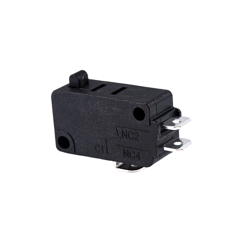
A micro switch is a small mechanical switch with a fast action mechanism, which is widely used in household appliances, industrial automation, automotive electronics, medical equipment, and other fiel...View More >>
-
Push button switches are widely used in various control systems with their diverse structural designs, high-strength material selection, and excellent performance. The products are available in a vari...View More >>
-
The internal structure of the piano key switch mostly adopts a mechanical or light-touch design. Some high-end models use capacitive sensing technology to achieve contactless operation, thereby improv...View More >>
-
The baby stroller gear switch is an innovative product independently developed by our company. We have applied for invention patents both domestically and internationally, which fully demonstrates the...View More >>
-
The knob switch adopts a high-sensitivity rotary contact structure, which has smooth operation and clear positioning, ensuring that every adjustment is accurate. The product has excellent durability a...View More >>
-
The KM trigger switch is a universal high-current switch designed for high-power power tools, with excellent current carrying capacity and stable performance. The internal fast-action structure ensure...View More >>
-
A door control switch, also known as a door magnetic switch or door status sensor, is a key electrical component widely used in industrial control, security systems, intelligent building automation, a...View More >>
-
The wiring harness is an overall wiring assembly that integrates multiple wires, cables, terminals, and connectors according to specific electrical design and mechanical structure requirements. It is ...View More >>
-
PCB control board is one of the indispensable core components in modern electronic devices. As the brain of the control system, it is widely used in many fields such as industrial automation, consumer...View More >>
NEWS
 Home / News / Industry News / Micro Switches Explained: How They Work, What the Specs Mean, and How to Choose the Right One
Micro Switches Explained: How They Work, What the Specs Mean, and How to Choose the Right One
 2026.04.01
 Industry News
Content
- 1 What Micro Switches Are and Why the Snap-Action Mechanism Matters
- 2 Micro Switch Anatomy: Terminals, Actuator Types, and Body Sizes
- 3 Key Electrical Ratings and What They Mean in Practice
- 4 Where Micro Switches Are Used: Industrial and Commercial Applications
- 5 Critical Micro Switch Parameters: Operating Force, Differential Travel, and Pretravel
- 6 Environmental Ratings, Sealing, and Temperature Considerations
- 7 How to Select the Right Micro Switch: A Practical Framework
What Micro Switches Are and Why the Snap-Action Mechanism Matters
A micro switch — formally called a miniature snap-action switch — is a precision electromechanical switch that operates through a spring-loaded internal mechanism designed to change state rapidly and with a very defined, repeatable actuation point. The defining characteristic is the snap-action: the internal contact moves abruptly and completely from one position to the other the instant the actuating force reaches a precise threshold, regardless of how slowly or quickly the external actuator is being pressed. This snap-action behavior is not incidental — it is the engineering principle that makes micro switches fundamentally different from simple contact switches and gives them their exceptional reliability and consistency in demanding applications.
The mechanism inside a micro switch centers on an over-center spring blade — a precisely formed piece of spring steel that stores elastic energy as it is deflected by the actuating plunger. When the deflection reaches the critical point, the blade snaps over center and drives the moving contact from the normally closed (NC) position to the normally open (NO) position almost instantaneously, typically in under one millisecond. This rapid contact travel means the contacts spend minimal time in a partially open state where arcing is most damaging. The result is a switch with dramatically longer contact life than a slow-wiping contact design, typically rated for 1 million to 10 million mechanical operations depending on the model and load conditions.
The term "micro switch" is technically a trademarked brand name originally owned by Honeywell (formerly Micro Switch, a division of Honeywell), but it has become the generic descriptor for the entire category of miniature snap-action switches across the industry — much like how "Velcro" describes hook-and-loop fasteners generically. Today, micro switches are manufactured by dozens of companies worldwide including Omron, Cherry, Panasonic, ALPS, C&K, and many OEM producers, all building on the same fundamental snap-action operating principle.
Micro Switch Anatomy: Terminals, Actuator Types, and Body Sizes
Every micro switch shares a common set of functional elements, but the specific actuator type, body size, terminal configuration, and contact material vary significantly across models. Understanding these elements is essential to selecting the right switch for a given application — the wrong actuator geometry or an undersized contact rating will cause the switch to fail long before its rated life is reached.
Contact Terminals: COM, NO, and NC
Every micro switch has three electrical terminals: Common (COM), Normally Open (NO), and Normally Closed (NC). In the unactuated resting state, the COM terminal is connected to NC and disconnected from NO. When the actuator is pressed and the snap-action threshold is reached, COM transfers to NO and disconnects from NC. This three-terminal configuration makes every standard micro switch an SPDT device, offering full flexibility for circuit design. The NC terminal is used when the circuit should normally be energized and should open when the switch is triggered — common in safety interlocks and door sensing. The NO terminal is used when the circuit should be energized only when the switch is actively triggered — typical in position detection and counting applications. Connecting only two of the three terminals effectively creates an SPST switch in either normally-open or normally-closed configuration.
Actuator Styles and Their Applications
The actuator is the external part of the micro switch that converts mechanical motion from the application into the force that deflects the internal snap-action blade. The actuator style determines the direction of approach, the amount of overtravel allowed, and the geometric relationship between the switch body and the triggering mechanism. Selecting the wrong actuator style leads to misalignment, inconsistent actuation, or mechanical binding.
- Pin plunger (bare plunger): The simplest form — a small cylindrical pin extending from the switch body that is pressed directly downward. Used in tight-tolerance applications where the triggering cam or feature contacts the plunger tip precisely. Requires accurate alignment and has limited overtravel tolerance.
- Simulated roller plunger: A rounded or roller-tipped plunger that accommodates slight angular misalignment and allows a cam or ramp surface to approach from a shallower angle. The most widely used actuator type in industrial position detection and limit switch applications.
- Roller lever: A lever arm with a small roller wheel at its end, pivoting about the switch body. The lever provides mechanical advantage (reducing the force needed to actuate the switch), accommodates approaches from a wider angular range, and gives additional overtravel protection against damage from over-travel of the triggering mechanism.
- Leaf (wire) lever: A long, thin spring steel lever extending from the switch body. The extended length makes it extremely sensitive to small actuation forces and displacements — ideal for detecting the presence of lightweight objects like paper sheets, film, or thin plastic parts in a production line.
- Adjustable roller lever: A roller lever with a variable-length arm allowing the actuation point to be moved closer to or farther from the switch body — useful when the triggering feature distance cannot be precisely fixed during machine design.
Body Size Classes
Micro switches are manufactured in a range of standardized body sizes that define both physical dimensions and electrical rating classes. The three dominant categories are standard (full-size) micro switches with body dimensions around 28×16×10mm, capable of switching up to 15–25A; subminiature micro switches with bodies around 20×10×6mm, rated up to 3–5A; and ultra-subminiature (or miniature) switches with bodies as small as 8×6×4mm, rated for signal-level currents of 0.1–1A. The physical size generally correlates with contact current capacity because larger contacts dissipate heat from resistive losses more effectively and maintain lower contact resistance under higher current. Choosing a subminiature switch for a load that requires a standard-size switch rating is one of the most common and costly micro switch selection errors.
Key Electrical Ratings and What They Mean in Practice
Micro switch datasheets list multiple electrical ratings that can be confusing at first glance. Understanding what each rating means — and which one applies to your specific circuit — prevents both unsafe overloading and unnecessarily conservative over-specification that wastes budget and space.
| Rating Type | Typical Values | When It Applies |
|---|---|---|
| General purpose AC (resistive) | 10–15A at 125/250V AC | Switching resistive AC loads directly |
| Inductive AC (motor load) | 3–5A at 125/250V AC | Direct switching of AC motors or solenoids |
| DC resistive | 1–5A at 30V DC | Switching DC resistive loads directly |
| Pilot duty | 0.1–1A at 125V AC | Switching relay coils, PLC inputs, control signals |
| Gold contact (dry circuit) | 1mA–100mA at 5–30V DC | Signal-level inputs to microcontrollers and logic circuits |
The AC resistive rating is almost always the highest number on the datasheet and the one most prominently displayed — but it applies only to purely resistive AC loads like incandescent heaters and resistive heating elements. Switching an AC motor, solenoid, or transformer requires using the significantly lower inductive AC rating. Exceeding the inductive rating causes severe contact arcing at each switching cycle, rapidly eroding the contact surfaces and causing the switch to fail in a welded-closed or open-circuit condition far ahead of its rated life.
For low-level signal switching — connecting a micro switch output to a microcontroller GPIO pin, a PLC digital input, or a logic circuit — standard silver contacts may not be appropriate. Silver contacts require a minimum contact current of approximately 100mA to self-clean through normal arcing that removes surface oxide films. Below this current, silver contacts develop insulating oxide layers that cause intermittent open-circuit faults even when the switch appears to be mechanically actuated correctly. Gold-plated or gold-alloy contacts are specifically designed for dry circuit operation at currents below 100mA and maintain reliable electrical contact throughout their mechanical life without the self-cleaning arc.
Where Micro Switches Are Used: Industrial and Commercial Applications
Micro switches appear in virtually every sector of manufacturing, automation, consumer products, and commercial equipment. Their combination of precise, repeatable actuation, long mechanical life, compact size, and low cost makes them the default choice for position sensing, safety interlocking, and limit detection tasks across an enormous range of machines and products.
Industrial Automation and Limit Switching
In industrial machinery, micro switches serve as limit switches that detect when a moving part — a conveyor carriage, a press ram, a robot axis, or a sliding door — has reached the end of its travel range. The switch signals the machine controller to stop the drive, preventing mechanical overtravel that would damage the machine or the workpiece. For this application, the roller lever actuator is most common because it accommodates the angular approach of a moving cam or dog and provides overtravel protection if the machine controller response is slightly delayed. Industrial-grade micro switches for this service are typically rated IP67 for protection against coolant and wash-down water, mounted in a robust metal housing, and specified with silver-alloy contacts for the moderate switching currents involved in controlling PLC inputs and relay coils.
Safety Interlocks and Door Guards
Machine safety interlocks use micro switches — often in a normally closed configuration on the NC terminal — to monitor whether protective guards, access doors, or safety covers are properly closed before and during machine operation. When the guard is opened, the switch actuator is released, the NC contact opens, and the safety circuit cuts power to the hazardous machine function. This fail-safe wiring approach means that any switch failure, wiring break, or guard opening interrupts the safety circuit — the machine stops rather than continuing to run dangerously. Safety-rated micro switches for interlock service are typically specified to IEC 60947-5-1 or UL 508 standards, with forced-guided contacts or positive opening operation mechanisms that prevent contact welding from causing an undetected dangerous failure mode.
Consumer Appliances and Electronics
Micro switches appear inside countless consumer products, often performing functions the user is unaware of. Microwave oven door interlocks use three stacked micro switches to verify the door is fully latched before allowing the magnetron to energize — a critical safety function regulated by international appliance standards. Washing machine lid switches cut motor power when the lid is opened during the spin cycle. Refrigerator door switches activate interior lighting and can signal the control board to adjust compressor cycling based on door-open frequency. Computer mice have used micro switches as primary button click mechanisms for decades — the satisfying click of a quality mouse button is the snap-action of a subminiature micro switch underneath the button cap. Vending machines, photocopiers, printers, and coffee machines all contain multiple micro switches for door sensing, paper path detection, dispensing confirmation, and position feedback.
Automotive Applications
Automotive micro switches control functions including door ajar warning lights, trunk and hood open indicators, brake light activation (the brake pedal switch is almost universally a micro switch), clutch pedal position sensing, and gear selector position detection in automatic transmissions. Automotive-grade micro switches are specified to operate reliably across extreme temperature ranges — typically −40°C to +125°C — and must maintain consistent actuation force and travel parameters over hundreds of thousands of operating cycles without adjustment. The gold-contact variants are used in automotive body control module inputs where the switching current is milliamp-level signal current rather than direct load current.
Critical Micro Switch Parameters: Operating Force, Differential Travel, and Pretravel
The mechanical parameters of a micro switch are as important as its electrical ratings for ensuring correct performance in a given application. These parameters define exactly where and how the switch actuates and releases, which determines the precision of position detection and the reliability of the switching action over the life of the machine.
Operating Force (OF) and Release Force (RF)
Operating force is the force that must be applied to the actuator to cause the snap-action switching event — the point at which COM transfers from NC to NO. Release force is the reduced force at which the actuator returns and the switch resets to its original state as the actuating mechanism withdraws. The difference between these two values is the hysteresis of the switch, which ensures it does not chatter (rapidly toggle between states) when the actuating mechanism is near the actuation point. Operating forces range from under 0.5N for sensitive leaf lever switches designed for detecting lightweight objects, to 10N or more for heavy-duty plunger switches in industrial machinery that must resist accidental actuation from vibration.
Pretravel, Overtravel, and Differential Travel
Pretravel (PT) is the distance the actuator moves from its free resting position to the point where snap-action occurs. Overtravel (OT) is the additional travel available beyond the snap-action point before the actuator reaches its mechanical stop — this overtravel must be accommodated by the application's triggering geometry to avoid damaging the switch through excessive force. Differential travel (DT) is the distance the actuator must move back toward its resting position after snap-action before the switch resets — it is always smaller than the pretravel, creating the hysteresis behavior described above. These three parameters together define the geometric precision window within which the switch functions correctly, and they must be matched to the motion resolution and positional tolerance of the machine or mechanism being sensed.
Environmental Ratings, Sealing, and Temperature Considerations
Standard micro switches without sealing are appropriate only for clean, dry indoor environments. The open actuator aperture and terminal area allow ingress of moisture, dust, oil mist, and cleaning fluids that contaminate contacts, corrode terminals, and cause mechanical interference with the snap-action mechanism. For any application involving exposure to these conditions, sealed micro switches with appropriate IP ratings are required.
IP67-rated micro switches use a combination of elastomeric boot seals over the actuator, sealed terminal covers or potted terminal blocks, and sealed body joints to achieve dust-tight and one-meter immersion protection. These are standard for industrial machinery, outdoor equipment, and food processing installations. IP67 switches are compatible with high-pressure wash-down cleaning procedures used in food and beverage and pharmaceutical manufacturing. For immersion or continuous high-pressure wash-down beyond IP67, IP68 or IP69K rated units are required — the IP69K rating specifically certifies resistance to high-temperature, high-pressure steam cleaning at close range, which is demanded in many food production environments.
Operating Temperature Range
Standard micro switches are rated for operating temperatures from −25°C to +85°C, which covers the majority of indoor industrial and commercial applications. High-temperature variants extend the upper limit to +125°C or +155°C for applications near heat sources — ovens, engine compartments, casting machines, and hot material handling equipment. Low-temperature performance is critical in refrigeration equipment and cold chain logistics — at temperatures below −25°C, standard elastomeric seals become rigid and lose their sealing effectiveness, and some contact lubricants used in the snap-action mechanism become viscous enough to dampen or prevent switching. Switches specified for cold-temperature service use low-viscosity synthetic lubricants and seal materials rated to −40°C or lower.
How to Select the Right Micro Switch: A Practical Framework
Selecting a micro switch for a new application or replacing a failed unit requires working through a logical sequence of parameters. Skipping steps or relying only on the headline current rating leads to poor performance and premature failure. The following framework covers the essential decisions in order of priority.
- Define the load type and current: Determine whether the switch will directly switch a load (and whether that load is resistive AC, inductive AC, DC resistive, or DC inductive) or will switch a signal-level input. This determines the required contact material (silver for power loads, gold for dry circuits) and the applicable electrical rating column on the datasheet.
- Choose the actuator type: Match the actuator to the geometric approach of the triggering mechanism — direction of approach, available actuation force, permissible overtravel, and alignment tolerance. A roller lever is the most forgiving choice for general industrial use; a pin plunger is appropriate for precision PCB-mount sensing with accurate mechanical positioning.
- Select the body size: Match the body size to the current rating required. Do not use a subminiature switch for a current load that requires a standard-size switch — size down only when the application current clearly falls within the smaller switch's rating with margin.
- Specify the operating force range: Ensure the triggering mechanism can reliably deliver the switch's operating force throughout the machine's life, including worst-case conditions such as low temperature, worn cam surfaces, and reduced spring force in the actuating mechanism.
- Determine the IP rating: Match to the harshest environmental condition the switch will face — moisture, dust, chemical spray, or wash-down. IP67 is a practical minimum for most industrial machine installations.
- Check the operating temperature range: Confirm the switch's rated temperature range covers the full ambient and local heat-soak temperature the switch will experience in the installed location — not just the nominal ambient temperature of the room.
- Confirm the terminal type and mounting style: Verify that the switch's solder lug, quick-connect, or screw terminals match the wiring approach, and that the mounting hole pattern fits the available installation space and panel material thickness.
When replacing a failed micro switch, do not assume a direct physical replacement from another manufacturer will be electrically and mechanically equivalent. Confirm that the replacement matches the original in actuator type, operating force, pretravel distance, contact rating, and terminal configuration. Minor differences in pretravel or operating force can cause the replacement switch to actuate at a significantly different position than the original, leading to machine timing errors or safety interlock gaps that may not be immediately obvious during commissioning.


A Appliance Switches Manufacturer that has been focusing on the development, production and sales of Switches for 21 years;
Products Links
Contact Information
Tel: +86-021-33752188
Phone: +86-15902103688
E-Mail: [email protected]
[email protected]
[email protected]Address: No. 580 Shenzhou Road, Fengxian District, Shanghai, China

