


 English
  русский
  Español
  Deutsch
  عربى
عربى -
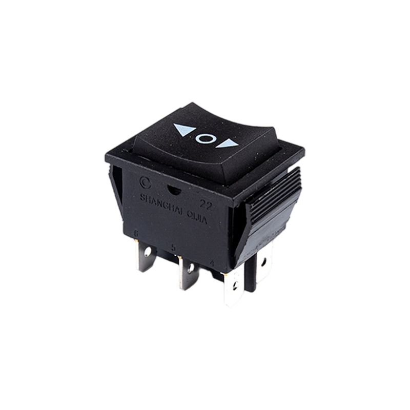
A Rocker Switch is a compact and easy-to-operate manual control component. Its unique rocker-style actuation, combined with a toggle or momentary reset function, allows users to quickly switch circuit...View More >>
-
A micro switch is a small mechanical switch with a fast action mechanism, which is widely used in household appliances, industrial automation, automotive electronics, medical equipment, and other fiel...View More >>
-
Push button switches are widely used in various control systems with their diverse structural designs, high-strength material selection, and excellent performance. The products are available in a vari...View More >>
-
The internal structure of the piano key switch mostly adopts a mechanical or light-touch design. Some high-end models use capacitive sensing technology to achieve contactless operation, thereby improv...View More >>
-
The baby stroller gear switch is an innovative product independently developed by our company. We have applied for invention patents both domestically and internationally, which fully demonstrates the...View More >>
-
The knob switch adopts a high-sensitivity rotary contact structure, which has smooth operation and clear positioning, ensuring that every adjustment is accurate. The product has excellent durability a...View More >>
-
The KM trigger switch is a universal high-current switch designed for high-power power tools, with excellent current carrying capacity and stable performance. The internal fast-action structure ensure...View More >>
-
A door control switch, also known as a door magnetic switch or door status sensor, is a key electrical component widely used in industrial control, security systems, intelligent building automation, a...View More >>
-
The wiring harness is an overall wiring assembly that integrates multiple wires, cables, terminals, and connectors according to specific electrical design and mechanical structure requirements. It is ...View More >>
-
PCB control board is one of the indispensable core components in modern electronic devices. As the brain of the control system, it is widely used in many fields such as industrial automation, consumer...View More >>
NEWS
 Home / News / Industry News / A Technical Guide to Selecting and Integrating High-Performance Rocker Switches
A Technical Guide to Selecting and Integrating High-Performance Rocker Switches
 2025.12.18
 Industry News
Content
Understanding Rocker Switch Actuation and Circuitry
Rocker switches are defined by their "see-saw" motion, where pressing one side of the actuator raises the other to open or close an electrical circuit. Unlike toggle switches that protrude significantly, rocker switches offer a lower profile, making them less susceptible to accidental trippings in high-traffic environments. Internally, the mechanism relies on a spring-loaded pivot that snaps into position, providing both tactile and audible feedback to the user. This snap-action is critical because it minimizes electrical arcing by ensuring the contacts move quickly between states, thereby extending the operational lifespan of the component.
When selecting a rocker switch, the internal circuitry configuration is the most vital technical specification. These are generally categorized by their poles (the number of separate circuits the switch controls) and throws (the number of positions each pole can connect to). Understanding these abbreviations ensures the switch matches the logical requirements of your device hardware.
| Circuit Abbreviation | Full Name | Typical Application |
| SPST | Single Pole, Single Throw | Simple On/Off power control |
| SPDT | Single Pole, Double Throw | Switching between two functions (e.g., High/Low) |
| DPST | Double Pole, Single Throw | Controlling two circuits simultaneously (e.g., Hot and Neutral) |
| DPDT | Double Pole, Double Throw | Complex motor reversing or dual-source switching |
Critical Environmental and Electrical Ratings
Industrial and outdoor applications require rocker switches that can withstand harsh conditions. One of the primary considerations is the Ingress Protection (IP) rating, which determines the switch's resistance to dust and moisture. For marine dashboards or medical equipment subject to wash-downs, an IP65 or IP67 rating is standard. These switches often feature internal silicone gaskets or ultrasonic welding to prevent liquids from reaching the internal copper or silver contacts, which would otherwise lead to corrosion or short-circuiting.
Electrical Load Considerations
It is essential to distinguish between Resistive and Inductive loads when evaluating a rocker switch. Resistive loads, like heaters or incandescent bulbs, are straightforward. However, inductive loads, such as motors or transformers, create a significant "inrush current" when the switch is first closed. If a switch is not rated for the specific peak amperage of an inductive load, the contacts may weld together, causing permanent failure. Always verify the AC vs. DC voltage ratings, as DC arcs are harder to extinguish and require specialized switch internal designs.
Design Features and User Interface Customization
Modern rocker switches serve as a primary touchpoint for users, meaning aesthetics and visibility are just as important as mechanical reliability. Illumination options play a huge role in functional safety, allowing users to identify the status of a machine from a distance or in low-light conditions. These can be wired to be "dependent" (light stays on when the switch is pushed) or "independent" (light is controlled by a separate circuit, such as a master dash light).
- Momentary vs. Maintained Action: Maintained switches stay in position until pressed again, while momentary (reset) switches only complete the circuit as long as pressure is applied.
- Mounting Styles: Snap-in mounting is the most common for plastic panels, whereas screw-mount frames are preferred for heavy-duty metal industrial enclosures.
- Termination Types: Options include quick-connect tabs for easy wiring, solder lugs for permanent vibration-resistant connections, or PCB pins for direct mounting to circuit boards.
- Laser Etching: Custom icons or text can be etched onto the rocker face to provide clear instructions, improving the ergonomics and safety of the control panel.
Installation Best Practices for Longevity
To ensure the maximum cycle life of a rocker switch, proper installation is paramount. Over-tightening or using a panel cutout that is slightly off-dimension can put mechanical stress on the switch housing, leading to "sticky" actuation or cracked casings over time. When wiring, ensure that the gauge of the wire is appropriate for the current load; undersized wires can generate heat that transfers to the switch terminals, potentially melting the internal plastic supports. For high-vibration environments, using insulated female disconnects with locking tabs ensures that the connection remains secure through years of operation.


A Appliance Switches Manufacturer that has been focusing on the development, production and sales of Switches for 21 years;
Products Links
Contact Information
Tel: +86-021-33752188
Phone: +86-15902103688
E-Mail: [email protected]
[email protected]
[email protected]Address: No. 580 Shenzhou Road, Fengxian District, Shanghai, China

