


 English
  русский
  Español
  Deutsch
  عربى
عربى -
A Rocker Switch is a compact and easy-to-operate manual control component. Its unique rocker-style actuation, combined with a toggle or momentary reset function, allows users to quickly switch circuit...View More >>
-
A micro switch is a small mechanical switch with a fast action mechanism, which is widely used in household appliances, industrial automation, automotive electronics, medical equipment, and other fiel...View More >>
-
The baby stroller gear switch is an innovative product independently developed by our company. We have applied for invention patents both domestically and internationally, which fully demonstrates the...View More >>
-
Push button switches are widely used in various control systems with their diverse structural designs, high-strength material selection, and excellent performance. The products are available in a vari...View More >>
-
The internal structure of the piano key switch mostly adopts a mechanical or light-touch design. Some high-end models use capacitive sensing technology to achieve contactless operation, thereby improv...View More >>
-
The knob switch adopts a high-sensitivity rotary contact structure, which has smooth operation and clear positioning, ensuring that every adjustment is accurate. The product has excellent durability a...View More >>
-
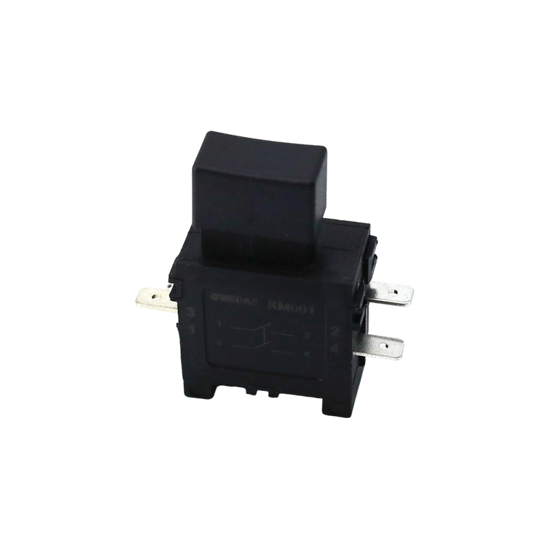
The KM trigger switch is a universal high-current switch designed for high-power power tools, with excellent current carrying capacity and stable performance. The internal fast-action structure ensure...View More >>
-
A door control switch, also known as a door magnetic switch or door status sensor, is a key electrical component widely used in industrial control, security systems, intelligent building automation, a...View More >>
-
The wiring harness is an overall wiring assembly that integrates multiple wires, cables, terminals, and connectors according to specific electrical design and mechanical structure requirements. It is ...View More >>
-
PCB control board is one of the indispensable core components in modern electronic devices. As the brain of the control system, it is widely used in many fields such as industrial automation, consumer...View More >>
NEWS
 Home / News / Industry News / Trigger Switches: Types, How They Work, Key Specs & How to Choose the Right One
Trigger Switches: Types, How They Work, Key Specs & How to Choose the Right One
 2026.05.25
 Industry News
Content
- 1 What Is a Trigger Switch and How Does It Work?
- 2 Main Types of Trigger Switches
- 3 Key Electrical Specifications Explained
- 4 Common Applications of Trigger Switches Across Industries
- 5 How to Replace a Trigger Switch: Step-by-Step
- 6 Troubleshooting Common Trigger Switch Problems
- 7 How to Choose the Right Trigger Switch for a New Design or Replacement
What Is a Trigger Switch and How Does It Work?
A trigger switch is an electromechanical control device designed to be actuated by a squeezing finger motion — mimicking the action of pulling a trigger — to open or close an electrical circuit. Unlike a conventional push-button or toggle switch that operates with a simple on/off action, most trigger switches are engineered to provide proportional or variable output: the further the trigger is depressed, the more current or voltage is delivered to the connected load. This proportional control is what makes trigger switches fundamental to power tools, garden equipment, industrial machinery, and a wide range of consumer and professional devices where smooth, intuitive speed or power modulation is required.
Internally, a trigger switch consists of a spring-loaded actuator mechanism connected to electrical contacts or a variable resistance element. In the simplest on/off trigger switches, depressing the trigger pushes a plastic actuator that closes a pair of electrical contacts, completing the circuit. In variable speed trigger switches — the more common type in modern power tools — the trigger actuator moves a sliding carbon contact across a resistive element (a potentiometer) or varies the position of a wiper on a printed circuit board, changing the resistance signal sent to a motor speed control circuit. More advanced electronic trigger switches use Hall effect sensors or optical encoders to detect trigger position without mechanical contact, providing longer service life and more precise proportional control.
Most trigger switches also incorporate a locking mechanism — commonly called a lock-on or lock-off button — positioned adjacent to the trigger. When engaged, this lock holds the trigger in the depressed position so the tool can run continuously without the operator maintaining grip pressure, useful for sustained operations like routing, sanding, or sawing. The safety implications of this feature are significant, and many jurisdictions and application standards mandate specific lock-on/lock-off configurations depending on tool type and hazard level.
Main Types of Trigger Switches
Trigger switches are not a single product — they span a broad family of designs differentiated by their electrical architecture, control method, current rating, and intended application. Understanding the key types prevents mismatched replacements and ensures correct specification for new designs.
On/Off Trigger Switches
The simplest trigger switch type provides only two states: open (circuit off) and closed (circuit on). There is no intermediate position — the switch snaps closed at a defined actuation force and snaps open when the trigger is released. On/off trigger switches are used in applications where variable speed control is unnecessary or undesirable: circular saw triggers, reciprocating saws, demolition hammers, and some pneumatic tool controls. They are mechanically robust, electrically straightforward, and easier to manufacture to high current ratings than variable speed variants. A well-designed on/off trigger switch has a crisp, positive actuation feel that gives the operator clear tactile feedback that the circuit has been engaged, reducing the risk of unintentional partial actuation.
Variable Speed Trigger Switches
Variable speed trigger switches — sometimes called speed control trigger switches or proportional trigger switches — are the most widely used type in cordless and corded power tools. They combine the mechanical trigger actuator with an electronic speed control module that reads trigger position and modulates the voltage or current supplied to the motor accordingly. In brushed DC motor tools, this is achieved through pulse width modulation (PWM) — the electronic module switches the motor supply on and off at high frequency, with the duty cycle (percentage on-time) varying in proportion to trigger position. In brushless motor tools, the trigger position signal is sent to a dedicated motor controller IC that generates the phase commutation signals for the BLDC motor at the appropriate speed setpoint. Variable speed trigger switches for drills, drivers, jigsaws, and routers allow the operator to start slowly for controlled material engagement and ramp up to full speed for bulk material removal — a control capability that significantly improves work quality and reduces material damage.
Reversible Trigger Switches
Reversible trigger switches incorporate a direction-reversing mechanism — typically a sliding or rotating reverse button positioned above or alongside the trigger — that changes the polarity of the motor supply or swaps the phase sequence in brushless systems, reversing motor rotation direction. These switches are standard in cordless drills and screwdrivers, where forward rotation drives fasteners in and reverse rotation backs them out. The reverse selector on a reversible trigger switch is typically designed so that direction can only be changed when the trigger is fully released — an interlock that prevents the motor from being reversed under load, which would cause mechanical shock and potential damage to the gearbox or the workpiece. Reversible trigger switches are more complex internally than non-reversible types and are generally rated for lower maximum continuous current due to the additional switching contacts and internal wiring required for direction reversal.
Paddle Trigger Switches
Paddle trigger switches use a broad, flat actuator paddle rather than a narrow finger trigger, designed to be actuated by the palm or multiple fingers simultaneously. They are common in angle grinders, belt sanders, and other tools where the operator grips the tool body rather than a pistol-grip handle. The larger actuation surface of a paddle trigger distributes the actuation force over a wider area, reducing finger fatigue during sustained operation. Many paddle switches incorporate a safety paddle or deadman feature — the switch only stays closed when the operator actively maintains pressure, and releases immediately if grip is lost, providing an important safety function for high-torque rotating tools.
Electronic Trigger Switches with Soft-Start
Premium power tool trigger switches for routers, planers, and high-power grinders incorporate soft-start electronics within the switch assembly itself. When the trigger is first depressed, the soft-start circuit ramps motor speed up gradually over 0.5–2 seconds rather than applying full voltage instantaneously. This eliminates the violent startup torque reaction that occurs when a high-power motor is energized at full voltage, which can cause the tool to twist suddenly in the operator's hands. Soft-start trigger switches also reduce inrush current at startup, which extends motor brush life and reduces voltage sag on shared electrical circuits. The soft-start module is typically potted in epoxy within the switch body to protect it from the vibration, dust, and moisture present in tool operating environments.
Key Electrical Specifications Explained
Selecting or replacing a trigger switch requires matching electrical specifications precisely. An undersized switch will overheat and fail prematurely; an oversized switch may be physically incompatible or unnecessarily expensive. These are the parameters that matter most.
| Specification | What It Means | Practical Guidance |
| Voltage Rating (V) | Maximum supply voltage the switch can safely interrupt | Match to supply: 120V or 240V AC for corded tools; 18V–60V DC for cordless |
| Current Rating (A) | Maximum continuous current through switch contacts | Select rating ≥ tool's full-load current; consider stall current for sizing |
| Horsepower Rating (HP) | Motor load rating accounting for inductive switching loads | Always use HP-rated switches for motor loads — pure current ratings understate stress |
| AC/DC Rating | Whether switch is rated for AC, DC, or both | DC switching is harder on contacts than AC; never use AC-only switch on DC circuits |
| Speed Range (RPM) | Output speed range of variable speed module (0 to max RPM) | Must match motor's operating speed range for smooth, linear control feel |
| Mechanical Life (cycles) | Number of actuations before contact or mechanism failure | Professional tool switches typically rated 50,000–100,000 cycles minimum |
| IP Rating | Degree of dust and moisture ingress protection | IP54 minimum for outdoor tools; IP65 for washdown or wet environments |
| Terminal Configuration | Number, type, and position of electrical terminals | Must match existing wiring harness for direct replacement; verify before ordering |
Why Horsepower Rating Matters More Than Current Rating Alone
Motor loads are inductive, which means that when the switch opens and interrupts current flow, the collapsing magnetic field in the motor windings generates a voltage spike — often several times the supply voltage — across the opening contacts. This arc energy is far more destructive to switch contacts than the steady-state current flow during normal operation. Switch manufacturers address this by rating motor-load switches in horsepower (HP) rather than just amperes, with the HP rating derived from standardized motor load switching tests. A switch rated for 10A resistive load may only be suitable for a 1/3 HP motor load — roughly 2.5A at 120V — because of the arc suppression demands. Always specify or replace trigger switches using the HP rating that matches or exceeds the motor's nameplate horsepower, not just the current draw.
Common Applications of Trigger Switches Across Industries
Trigger switches appear in an enormous range of products across consumer, professional, and industrial segments. Understanding where they are used clarifies the design priorities — current capacity, variable control precision, environmental sealing, or ergonomic actuation force — that differ between applications.
Power Tools
Power tools are by far the largest application segment for trigger switches. Cordless drills and drivers, jigsaws, reciprocating saws, circular saws, angle grinders, routers, rotary hammers, and heat guns all use trigger switches as their primary operator control. In cordless drill-drivers — the highest-volume power tool globally — the trigger switch serves three functions simultaneously: it provides variable speed control from 0 to maximum RPM, it incorporates the forward/reverse selector for direction reversal, and it includes a lock-off safety button to prevent accidental startup. The trigger switch in a cordless drill typically handles 18–60V DC at currents up to 30–50A during stall conditions, in a package that must fit within a pistol-grip handle roughly 35–40 mm wide. This combination of high current capacity, variable control, and compact packaging represents one of the more demanding trigger switch design challenges in the consumer products sector.
Garden and Outdoor Power Equipment
Cordless and corded garden tools — hedge trimmers, string trimmers, leaf blowers, chainsaws, and lawn mowers — use trigger switches that must meet more stringent environmental requirements than indoor power tools. Exposure to rain, mud, grass clippings, and temperature extremes from -20°C to +50°C demands IP54 or IP65 rated switch housings with sealed contact chambers. Many garden tool trigger switches incorporate a two-handed safety interlock — a second switch or safety bar that must be depressed simultaneously with the trigger before the tool will start — to reduce the risk of accidental contact with cutting or rotating elements. These interlocks are often mandatory under product safety standards such as EN 60745 (Europe) and UL 62841 (North America) for handheld outdoor power tools.
Spray Equipment and Fluid Dispensing
Electric spray guns for paint, adhesive, and garden chemical applications use trigger switches to control the pump motor that pressurizes and delivers the fluid. In these applications, variable speed trigger control is essential — slow trigger depression at the start and end of a spray pass prevents blobs and runs at the edges, while full trigger depression maintains even coverage across the center of the surface. Trigger switches for spray equipment must be resistant to the specific solvents and chemicals in use: solvent-based paint and adhesive spray equipment requires switches with chemically resistant housing materials (acetal or nylon rather than ABS) and sealed contact chambers that prevent solvent vapor ingress, which could cause contact arcing or housing degradation.
Industrial and Material Handling Equipment
Industrial trigger switches are used as operator controls in electric hoists, cable reelers, motorized valves, industrial staplers, riveters, and assembly tools. These applications typically demand higher current ratings (20–60A), longer mechanical life (100,000–500,000 cycles), and greater resistance to vibration and shock than consumer-grade trigger switches. Industrial trigger switches are often designed to be field-repairable — with replaceable contact sets and modular electronic speed control modules — to minimize downtime in production environments. Compliance with IEC 60947 (industrial switchgear standards) and UL 508 (industrial control equipment) is typically required for switches used in formal industrial automation contexts.
Medical and Laboratory Devices
Handheld medical devices — surgical drills, dermatome instruments, dental handpieces, and laboratory homogenizers — use miniaturized trigger switches with precise, repeatable actuation forces and extremely smooth variable speed control. In these applications, the switch actuation force profile (the relationship between trigger displacement and output speed) is carefully engineered to provide intuitive, fatigue-free control during lengthy procedures. Medical trigger switches must also meet sterilization compatibility requirements — autoclave-compatible switches must withstand repeated steam sterilization at 134°C and 3 bar pressure without seal degradation or contact contamination. These demands make medical-grade trigger switches among the most technically sophisticated in the product category, typically produced by specialist suppliers to ISO 13485 quality management standards.
How to Replace a Trigger Switch: Step-by-Step
Trigger switch replacement is one of the most common power tool repairs, and doing it correctly extends tool life significantly compared to discarding the tool. The procedure applies broadly across most corded and cordless tools with minor variations.
- Disconnect power completely: Unplug the tool from the mains or remove the battery pack before opening any covers. For cordless tools, also discharge any residual energy by briefly squeezing the trigger after battery removal. This is a non-negotiable safety step — working on a live trigger switch with power connected can cause electric shock and unintended motor activation.
- Photograph the wiring before disconnection: Use a phone camera to take clear photographs of the switch wiring from multiple angles before touching any connections. Trigger switches often have four to six terminals with similarly colored wires, and reconnecting them incorrectly can reverse motor direction, bypass speed control, or create a short circuit. The photos are your wiring reference during reassembly.
- Open the tool housing: Remove the housing screws — typically Torx T10–T20 or Phillips PH2 — and separate the two halves of the handle. Note that many tool manufacturers use different screw lengths in different positions; keeping removed screws in a tray in the order they were removed avoids confusion during reassembly.
- Release and remove the old switch: Most trigger switches are retained in the handle by plastic clip tabs on the switch body that engage with recesses in the handle halves. Pressing the tabs inward with a small flat-blade screwdriver while pushing the switch toward the trigger opening releases it from the housing. Disconnect the wires by pulling the spade connectors or push-in connectors directly off the terminals — do not pull on the wire insulation.
- Verify replacement switch compatibility: Compare the replacement switch against the original, checking physical dimensions, terminal count and position, voltage and current ratings, and the presence or absence of a reverse function and lock-on feature. The replacement should ideally be the OEM part number or a direct equivalent specified by the replacement supplier to match the original. If substituting a non-OEM replacement, confirm that its terminal layout matches the existing wiring harness exactly.
- Connect and reassemble: Connect each wire to the corresponding terminal on the new switch, referring to your photographs. Push spade connectors fully onto terminals until they click or seat flush — a partially connected terminal will arc and overheat under load. Clip the new switch into the handle recess, route wires to avoid pinching between housing halves, and reassemble the housing screws to the manufacturer's recommended torque (typically 0.8–1.2 N·m for M4 thread-forming screws into plastic).
- Test before returning to service: Reconnect power and test the switch through its full range of motion — slow trigger depression, full depression, reverse operation if applicable, and lock-on if fitted — before using the tool on a workpiece. Verify that speed control is smooth and linear and that the motor runs in the correct direction in both forward and reverse. Any unexpected behavior (running in reverse when forward is selected, no speed variation, immediate full-speed startup) indicates a wiring error that must be corrected before use.
Troubleshooting Common Trigger Switch Problems
Most trigger switch failures produce characteristic symptoms that point clearly to the switch as the cause — or just as usefully, rule out the switch and redirect attention to the motor, wiring, or battery. Accurate diagnosis before ordering parts saves time and money.
Tool Runs at Full Speed Immediately on Trigger Depression
If a variable speed tool jumps to full speed from the first moment of trigger contact rather than ramping up proportionally with trigger travel, the speed control module within the switch has failed — typically due to a failed PWM transistor or a broken speed-control resistive element that has shorted to the maximum output position. The switch assembly must be replaced. Confirm the diagnosis by measuring resistance between the speed control output terminals with a multimeter as the trigger is slowly depressed: resistance should vary smoothly from maximum to minimum. A reading that snaps immediately to minimum (or stays fixed at any position) confirms module failure.
Tool Does Not Start Despite Trigger Being Depressed
A tool that fails to start when the trigger is fully depressed could indicate a failed trigger switch, a tripped thermal cutout in the motor, a faulty battery (for cordless tools), or broken wiring. To isolate the switch, use a multimeter set to continuity or resistance mode: probe the two main power terminals on the switch while slowly depressing the trigger. If the switch shows no continuity at full depression, the contacts have failed or the actuator mechanism is broken. If the switch tests good, investigate the motor thermal cutout (often a small cylindrical bimetal device in the motor winding) and the wiring harness for breaks near strain points at the cable entry and handle junction.
Intermittent Operation or Speed Fluctuation Under Load
Intermittent power loss or erratic speed under load that is not present at no-load usually indicates high-resistance contacts within the trigger switch — caused by carbon buildup, contact oxidation, or a worn sliding contact element in the speed control module. High-resistance contacts generate heat proportional to the square of current, so the problem manifests most severely under high-load conditions when current is greatest. Cleaning contacts with contact cleaner spray can temporarily restore performance, but the underlying contact wear that caused the resistance increase will continue — switch replacement is the reliable long-term fix. Intermittent faults that correlate with handle vibration or flex suggest a broken solder joint or cracked PCB within the switch assembly rather than contact wear.
Reverse Direction Not Working
If a reversible tool runs correctly in forward but does not reverse — or runs in the same direction regardless of the reverse selector position — the reverse switching contacts within the trigger switch have failed or the reverse actuator mechanism has broken. Reversing contacts in a trigger switch typically carry the full motor current during direction switching, making them subject to arc erosion. In some tool designs, the reverse function is handled by a separate small sub-switch that is physically distinct from the main trigger switch body and can be replaced independently; in others, it is integrated within the main switch assembly and the entire unit must be replaced.
How to Choose the Right Trigger Switch for a New Design or Replacement
Whether you are specifying a trigger switch for a new product design or sourcing a replacement for a tool in service, the following framework ensures you cover the parameters that determine fit, function, and longevity.
- Determine voltage and current requirements: Establish the supply voltage (AC or DC, and the voltage value) and the maximum continuous current the switch will carry under normal operating load. For motor loads, also determine the stall current — typically 5–10× the running current — and confirm the switch's horsepower rating covers the motor's nameplate output with at least 20% margin.
- Decide on control type: Determine whether simple on/off control is sufficient or whether variable speed control is required. If variable speed is needed, confirm whether the speed control will be handled within the switch assembly (integrated electronic module) or externally (the switch provides only a position signal to a separate motor controller). For brushless motor systems, an analog voltage output or PWM signal from the switch to an external BLDC controller is the typical architecture.
- Identify physical and ergonomic requirements: Specify the maximum external dimensions that will fit within the handle, the required actuation force range (typically 2–8 N for professional tools; lighter for medical or low-fatigue applications), trigger travel distance, and the position and type of lock-on/lock-off feature if required. For replacements, the new switch must match the original's mounting clip pattern and terminal positions exactly.
- Check regulatory and certification requirements: For tools sold in the EU, trigger switches and their assemblies must comply with the Low Voltage Directive (2014/35/EU) and carry CE marking. For North American markets, UL or CSA certification of the switch is required for tools submitted to UL 62841 or equivalent safety standards. Always request certification documentation from trigger switch suppliers and confirm that the certification covers the specific voltage, current, and load type of your application.
- Consider environmental and service life requirements: Specify IP rating based on the operating environment. Confirm mechanical life rating matches the expected duty cycle over the product's design life — a professional tool used 4 hours per day, 250 days per year, with an average of 20 trigger actuations per hour accumulates 20,000 cycles per year, so a 100,000-cycle rated switch provides a 5-year service life at that duty. For higher-duty applications, specify accordingly or select a switch with field-replaceable contact inserts to enable economic servicing.


A Appliance Switches Manufacturer that has been focusing on the development, production and sales of Switches for 21 years;
Products Links
Contact Information
Tel: +86-021-33752188
Phone: +86-13524812989
E-Mail: [email protected]
[email protected]
[email protected]Address: No. 580 Shenzhou Road, Fengxian District, Shanghai, China

