


 English
  русский
  Español
  Deutsch
  عربى
عربى -
A Rocker Switch is a compact and easy-to-operate manual control component. Its unique rocker-style actuation, combined with a toggle or momentary reset function, allows users to quickly switch circuit...View More >>
-
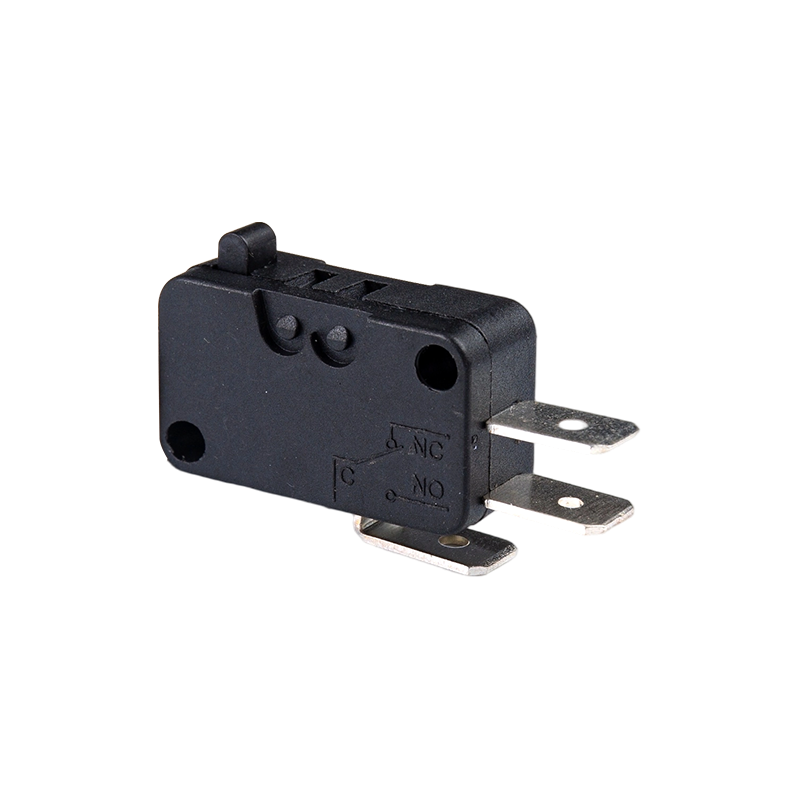
A micro switch is a small mechanical switch with a fast action mechanism, which is widely used in household appliances, industrial automation, automotive electronics, medical equipment, and other fiel...View More >>
-
Push button switches are widely used in various control systems with their diverse structural designs, high-strength material selection, and excellent performance. The products are available in a vari...View More >>
-
The internal structure of the piano key switch mostly adopts a mechanical or light-touch design. Some high-end models use capacitive sensing technology to achieve contactless operation, thereby improv...View More >>
-
The baby stroller gear switch is an innovative product independently developed by our company. We have applied for invention patents both domestically and internationally, which fully demonstrates the...View More >>
-
The knob switch adopts a high-sensitivity rotary contact structure, which has smooth operation and clear positioning, ensuring that every adjustment is accurate. The product has excellent durability a...View More >>
-
The KM trigger switch is a universal high-current switch designed for high-power power tools, with excellent current carrying capacity and stable performance. The internal fast-action structure ensure...View More >>
-
A door control switch, also known as a door magnetic switch or door status sensor, is a key electrical component widely used in industrial control, security systems, intelligent building automation, a...View More >>
-
The wiring harness is an overall wiring assembly that integrates multiple wires, cables, terminals, and connectors according to specific electrical design and mechanical structure requirements. It is ...View More >>
-
PCB control board is one of the indispensable core components in modern electronic devices. As the brain of the control system, it is widely used in many fields such as industrial automation, consumer...View More >>
NEWS

Micro Switches: Types, Specifications, Applications & Selection Guide
 2026.05.08
 Industry News
Content
- 1 What Are Micro Switches and How Do They Work?
- 2 Types of Micro Switches and Their Actuator Styles
- 3 Key Electrical Specifications You Need to Understand
- 4 Micro Switch Sizes: Subminiature, Miniature, and Standard
- 5 Common Applications of Micro Switches Across Industries
- 6 How to Select the Right Micro Switch for Your Application
- 7 Installation and Wiring Best Practices for Micro Switches
- 8 Troubleshooting Micro Switch Failures in the Field
What Are Micro Switches and How Do They Work?
Micro switches — also called miniature snap-action switches — are small electromechanical devices that open or close an electrical circuit in response to a very small physical movement or applied force. The defining characteristic of a micro switch is its snap-action mechanism: an internal spring-loaded contact system that switches states almost instantaneously once a specific actuating force threshold is reached, regardless of how slowly or quickly the actuator is moved. This snap-action behavior produces a clean, fast contact transition that minimizes arcing and contact bounce, making micro switches extremely reliable even after millions of operations.
The internal mechanism of a standard micro switch consists of a moving contact arm held under spring tension against a fixed common contact. When the actuator (usually a plunger, lever, or roller) is pressed to the operating point, the spring releases suddenly, snapping the moving contact from the normally closed (NC) position to the normally open (NO) position. When the actuating force is removed, the spring returns the contact to its original position at a slightly lower release force — a difference known as the differential travel. This differential travel is intentionally small, typically less than 0.5 mm on precision micro switches, which allows them to detect very precise positional changes.
Micro switches are used in virtually every industry — from consumer appliances and automotive systems to industrial machinery and aerospace equipment. Their combination of small size, high reliability, precise actuation, and low cost makes them one of the most widely specified switch types in electrical engineering.
Types of Micro Switches and Their Actuator Styles
Micro switches are available in a wide range of body sizes, electrical ratings, and actuator configurations. Selecting the right type starts with understanding which actuator style suits the mechanical interface in your application.
Pin Plunger (Standard Button) Type
The most basic actuator is a straight pin or button plunger that moves directly downward into the switch body. This type offers the most precise operating and release positions and the smallest differential travel, making it ideal for applications requiring exact position detection. Pin plunger micro switches are commonly used in CNC machines, vending machines, and industrial limit switch assemblies where a mechanical cam or dog presses the plunger at a specific point in travel.
Simulated Roller Lever Type
A lever arm with a roller at the tip extends from the switch body, allowing actuation from a wider range of angles. The roller reduces friction when a rotating cam or moving surface contacts the actuator, extending both the life of the switch and the cam surface. Roller lever micro switches are extremely common in conveyor systems, door interlock mechanisms, and automated packaging machinery.
Coil Spring Actuator Type
A flexible coil spring replaces the rigid lever arm, allowing actuation from virtually any direction without precise alignment between the actuator and the switch body. This makes coil spring micro switches useful in applications with unpredictable contact angles, such as safety guards, bumper-activated stop systems, and robotics collision detection.
Wobble Stick / Cat Whisker Type
A long, flexible wire or rod actuator responds to contact from almost any direction, making it highly sensitive and omnidirectional. These are often used as object detection sensors on automated guided vehicles (AGVs), in feeder systems, or anywhere a very light touch in any direction must trigger the switch.
Short Hinge Lever and Long Hinge Lever Types
Hinge levers pivot at the base of the switch body and translate linear force into rotational motion at the actuator. Short hinge levers offer faster actuation with less mechanical advantage, while long hinge levers require less force to actuate but have longer travel to the operating point. These are widely used in door position sensing, appliance lid detection, and safety interlock systems.
Key Electrical Specifications You Need to Understand
Reading a micro switch datasheet requires understanding a set of standard electrical parameters. Specifying the wrong ratings is a common cause of premature switch failure in the field.
| Parameter | Definition | Typical Range |
| Contact Rating (Resistive) | Maximum current at rated voltage for resistive loads | 0.1 A to 25 A |
| Voltage Rating | Maximum operating voltage AC or DC | 5 V DC to 480 V AC |
| Operating Force (OF) | Force required to actuate the switch to operating position | 0.5 N to 5 N (varies by type) |
| Release Force (RF) | Force at which switch resets to original position | Always less than OF |
| Differential Travel (DT) | Distance between operating position and release position | 0.1 mm to 1.5 mm |
| Mechanical Life | Total operations before mechanical failure (no load) | 1 million to 10 million ops |
| Electrical Life | Total operations at rated load before contact failure | 100,000 to 1 million ops |
| Contact Resistance | Resistance across closed contacts | Under 100 mΩ (initial) |
| Insulation Resistance | Resistance between open contacts or contacts to body | 100 MΩ minimum |
One important distinction when specifying micro switches is the difference between resistive and inductive load ratings. Inductive loads — motors, solenoids, relays — generate voltage spikes when the circuit opens, which causes significantly more contact wear and arcing than purely resistive loads. Most manufacturers derate the contact rating by 50–70% for inductive loads. If your micro switch is switching an inductive load, always check the inductive load rating specifically, or use a snubber circuit across the load to suppress voltage transients.
Micro Switch Sizes: Subminiature, Miniature, and Standard
Micro switches are manufactured in three general size categories, each suited to different space constraints and current-carrying requirements. Understanding the differences helps you match the right physical form factor to your design.
- Standard micro switches have body dimensions typically around 28 mm × 16 mm × 10 mm and support current ratings from 5 A to 25 A at 125–250 V AC. These are used in appliances, industrial control panels, HVAC equipment, and heavy-duty machinery where space is not severely constrained and higher current handling is needed.
- Miniature micro switches are smaller, typically around 20 mm × 10 mm × 6 mm, with ratings commonly in the 1–5 A range. They are widely used in consumer electronics, home appliances, automotive interior components, and medical devices where a balance of small size and reasonable current capacity is required.
- Subminiature micro switches are the smallest category, with body dimensions as small as 12 mm × 6 mm × 4 mm. They handle low currents, typically 0.1 A to 1 A, and are used in compact electronics, computer peripherals (mice, keyboards), telecommunications equipment, and precision instruments where every millimeter of PCB space matters.
When choosing a size category, never downsize purely to save space if the smaller switch cannot handle the electrical load. Running a micro switch above its rated current — even intermittently — causes rapid contact erosion, increased contact resistance, and early failure. Size to the electrical load first, then optimize for space within that constraint.
Common Applications of Micro Switches Across Industries
The versatility of miniature snap-action switches means they appear in an enormous range of products and systems. Here are the major application areas and what makes micro switches the right choice in each context.
Home Appliances
Micro switches are found inside microwave ovens (door interlock switches that cut power when the door opens), washing machines (lid position detection), refrigerators (door-open light activation), and dishwashers (door latch sensing). In these applications, the switch must survive hundreds of thousands of cycles over the product's lifetime while operating reliably in humid or thermally cycling environments. Sealed or waterproof micro switch variants are commonly specified for appliance use.
Industrial Machinery and Limit Switches
In factory automation, micro switches serve as the sensing elements inside industrial limit switch housings. They detect the end-of-travel positions of actuators, confirm that machine guards and safety doors are closed, and verify the position of tooling and fixtures. Industrial-grade snap-action switches for these applications are built into rugged metal or glass-filled nylon enclosures with IP67 or IP68 sealing ratings to withstand coolant, dust, and mechanical shock. Roller lever actuators are most common in this setting.
Automotive Systems
Modern vehicles use micro switches in brake pedal position sensing (brake light activation and transmission interlock), seatbelt buckle detection, door ajar indicators, sunroof position control, and HVAC control panels. Automotive micro switches must meet demanding specifications for vibration resistance, temperature cycling (−40°C to +125°C), and EMC compliance. Gold-plated contacts are commonly used in low-voltage automotive signal circuits to ensure reliable contact even at currents below 10 mA, where base metal contacts would suffer from oxide buildup.
Consumer Electronics and Computer Peripherals
The click inside a computer mouse is produced by a subminiature micro switch. Gaming mice use high-cycle-rated switches rated for 20–50 million clicks, and the choice of micro switch brand (Omron, Kailh, Huano) is a genuine differentiator in the gaming peripheral market. Micro switches also appear in keyboard stabilizers, game controllers, vending machine keypads, and point-of-sale terminals. In these low-current signal switching applications, contact reliability at milliamp levels is the primary specification driver.
Medical Devices and Laboratory Equipment
Medical-grade micro switches are used in infusion pumps (door and cartridge detection), surgical instruments, diagnostic equipment, and hospital bed position controls. These applications demand high reliability, cleanability, and in some cases biocompatibility of the switch housing material. Subminiature micro switches with stainless steel bodies and sealed housings are commonly specified. Traceability and documentation of component quality are also critical in medical device manufacturing to support regulatory submissions.
How to Select the Right Micro Switch for Your Application
With hundreds of micro switch variants available from major manufacturers like Omron, Honeywell, Cherry, Panasonic, and Crouzet, narrowing down the right part requires a systematic approach. Work through these selection criteria in order:
- Define the electrical load: Determine the voltage, current, and load type (resistive, inductive, lamp). Verify that the switch's contact rating at the actual load type meets your requirement with appropriate derating margins — typically 80% of rated capacity for continuous duty.
- Specify the required operating force and travel: Match the operating force to the mechanical force available from your actuating mechanism. Too high an operating force and the mechanism cannot reliably actuate the switch; too low and vibration or minor incidental contact may cause false triggering.
- Choose the actuator style: Select the actuator type that best matches the geometry and direction of the actuating force in your assembly — plunger, lever, roller, coil spring, or whisker as described earlier.
- Determine the required cycle life: Estimate the total number of switch operations over the product's service life and verify that both the mechanical life and the electrical life ratings exceed this number with an adequate safety margin (typically 2× minimum).
- Assess the environmental conditions: Consider operating temperature range, exposure to moisture, dust, oils, and chemicals. Select a sealing rating (IP rating) appropriate for the environment. For outdoor or washdown environments, IP67-rated sealed micro switches are the minimum appropriate specification.
- Check contact material for low-current applications: If the switch will carry signals below 100 mA, specify gold-clad or gold-plated contacts. Silver contacts form oxide layers at low currents that can create intermittent open circuits — a common and frustrating field failure mode that is entirely avoidable with the correct contact material specification.
Installation and Wiring Best Practices for Micro Switches
Even the best micro switch will fail prematurely if it is installed incorrectly. These practical guidelines help ensure long service life and reliable operation in the field.
Correct Actuator Alignment and Over-Travel
The actuating force must be applied in the correct direction relative to the switch body — most plunger-type micro switches require force applied perpendicular to the plunger axis within ±5° to avoid side-loading the plunger, which accelerates wear and can bend or jam the actuator. The mechanical stop in your assembly must also limit the total actuator travel to within the switch's specified over-travel range. Exceeding maximum over-travel physically damages the internal mechanism. In practice, design your cam or actuating dog to provide 50–70% of the maximum rated over-travel as the nominal operating condition, leaving margin for manufacturing tolerances and component wear.
Terminal Connection Methods
Micro switches are available with solder terminals, quick-connect (faston) terminals, PCB pin terminals, and screw terminals. For solder terminal types, use rosin-core solder and avoid applying heat for more than 3 seconds per terminal to prevent heat damage to the switch body. For screw terminal types, observe the manufacturer's specified torque values — overtorquing strips threads, while undertorquing results in loose connections that cause intermittent contact and can arc under load. For high-vibration environments, use locking terminals or apply thread-locking compound per the manufacturer's guidance.
Wiring the Correct Contact Configuration
Most micro switches provide three terminals: Common (C), Normally Open (NO), and Normally Closed (NC). Choosing the correct contact configuration for your circuit logic matters both for function and for switch life. For circuits that are closed most of the time and only open briefly (like a safety interlock), connecting to the NC terminal means the contacts carry current continuously. For circuits that are open most of the time and close briefly (like a trigger signal), the NO terminal is the right choice. Minimizing the total time the contacts carry current under load reduces contact erosion and extends electrical life.
Troubleshooting Micro Switch Failures in the Field
When a micro switch fails in service, diagnosing the root cause correctly is essential to choosing the right corrective action — whether that means a direct replacement, an upgraded specification, or a redesign of the mechanical interface.
- Contact welding (switch stuck closed): Caused by excessive inrush current at the moment of contact closure, especially with capacitive or motor loads. Fix by derating the switch, adding a current-limiting resistor, or selecting a switch with a higher inrush current rating and silver cadmium oxide contacts designed for high-inrush applications.
- Contact erosion (high resistance or intermittent open): Caused by arcing at contact opening, especially on inductive loads. Fix by adding a snubber circuit (RC network across the contacts for AC loads, or a flyback diode across the inductive load for DC circuits) to suppress voltage transients that cause arcing.
- Intermittent signal at low current: Almost always caused by contact oxidation on silver contacts in a low-current circuit. Fix by replacing with a gold-contact variant of the same switch type.
- Broken actuator or lever: Caused by side-loading, over-travel beyond the specified limit, or impact loads. Fix by correcting actuator alignment, adding a mechanical stop to limit over-travel, or selecting a switch with a more robust actuator style for the application.
- Switch fails to actuate consistently: Often caused by actuating force being too close to the operating force threshold, so manufacturing variation or wear causes intermittent actuation. Fix by redesigning the actuating mechanism to provide 30–50% more force than the switch's rated operating force at the nominal operating condition.
Keeping records of failure mode, operating hours, and operating conditions when replacing micro switches in the field builds a valuable data set for refining specifications and improving design reliability over successive product generations.


A Appliance Switches Manufacturer that has been focusing on the development, production and sales of Switches for 21 years;
Products Links
Contact Information
Tel: +86-021-33752188
Phone: +86-15902103688
E-Mail: [email protected]
[email protected]
[email protected]Address: No. 580 Shenzhou Road, Fengxian District, Shanghai, China

